
Tutorial for open windows
| Topic |
|---|
| Architecture |
| Level |
| Beginner |
| Time to complete |
| 60 minutes |
| Authors |
| vocx |
| FreeCAD version |
| 0.18 or greater |
| Example files |
| none |
| See also |
| None |
Introduction
This tutorial shows how to place Arch Windows and Doors in a building model, how to display them as open in the 3D view, and how to create a 2D drawing (plan and elevation projection) for the model. It uses the Draft Workbench, the Arch Workbench, and the TechDraw Workbench.
Common tools used are: Draft Grid, Draft Snap, Draft Wire, Arch Wall, Arch Window, Arch SectionPlane, and TechDraw ArchView.
See also the following page for some videos on how to work with windows and doors.
Setup
1. Open FreeCAD, create a new empty document, and switch to the Arch Workbench.
2. Make sure your units are set correctly in the menu Edit → Preferences → General → Units. For example, MKS (m/kg/s/degree) is good for dealing with distances in a typical building; moreover, set the number of decimals to 4, to consider even the smallest fractions of a meter.
3. Use the Draft ToggleGrid button to show a grid with enough resolution. You can change the grid appearance in the menu Edit → Preferences → Draft → Grid and snapping → Grid. Set lines at every 50 mm, with major lines every 20 lines (every meter), and 1000 lines in total (the grid covers an area of 50 m x 50 m).
4. Zoom out of the 3D view if you are too close to the grid.
Now we are ready to create a simple building with closed walls, two doors and two windows.
Placing a wall
5. Use the Draft Wire tool to create a closed wire. Go counterclockwise.
- 5.1. First point in (0, 0, 0); in the dialog enter 0 m Enter, 0 m Enter, 0 m Enter.
- 5.2. Second point in (3, 0, 0). Press X to constrain the movement to the X axis; enter the value 3 m Enter.
- 5.3. Third point in (3, 4, 0). Press Y to constrain the movement to the Y axis; enter the value 4 m Enter.
- 5.4. Fourth point in (0, 4, 0). Press X to constrain the movement to the X axis; enter the value - 3 m Enter.
- 5.5. Press O to close the Wire, and close the tool.
- 5.6. In the number pad press 0 to get an axonometric view of the model.
- Note: the points can also be defined with the mouse pointer by choosing intersections on the grid, with the help of the Draft Snap toolbar and the Draft Grid method.
6. Select the DWire and change the property DataMake Face to false.
7. Select the DWire and click the Arch Wall tool; the Wall is immediately created with a default width (thickness) of 0.2 m, and height of 3 m.
- Note: if the property DataMake Face of
DWireistrue, this step would create a solid block, instead of using only the contour ofDWire.
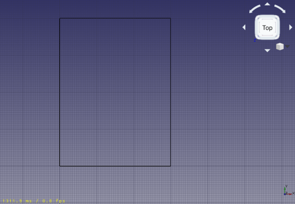
Base wire for the wall; it is a closed wire that doesn't make a face
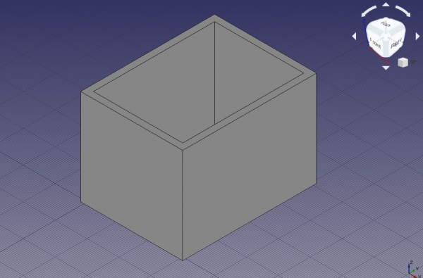
Wall constructed from the wire
Placing doors and windows
8. Click the Arch Window tool; as preset select Simple door, and change the height to 2 m.
- 8.1. Change the snapping to Draft Midpoint, and try selecting the bottom edge of the frontal wall; rotate the standard view as necessary to help you pick the edge and not the wall face; when the midpoint is active, click to place the door.
- 8.2. Click the Arch Window tool again, and place another door, but this time in the midpoint of the rear wall; rotate the standard view as necessary.
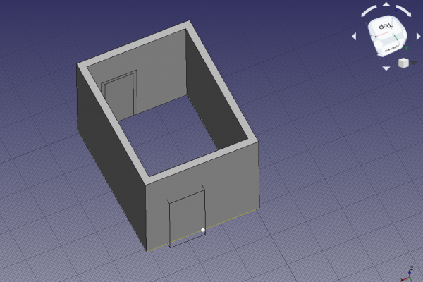
Snapping to the midpoint of the bottom edge of the wall to place the door
9. Click the Arch Window tool; as preset select Open 1-pane, and change the Sill height to 1 m.
- 9.1. Keep the snapping to Draft Midpoint, and try selecting the lower edge of the left side wall; rotate the standard view as necessary to help you pick the edge and not the wall face; when the midpoint is active, click to place the window.
- Note: the
Sill heightis the distance from the floor to the lower edge of the element. For doors theSill heightis usually 0 m as doors are normally touching the floor; on the other hand, windows have a usual separation of 0.5 m to 1.5 m from the floor.
- 9.2. Click the Arch Window tool again, and place another window, but this time in the midpoint of the right wall; rotate the standard view as necessary. This time make the window's width (length) 1.5 m, and again make the
Sill height1 m.
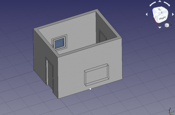
Snapping to the midpoint of the bottom edge of the wall to place the window
- Note: the
Sill heightparameter can only be set when initially creating the window with a preset. Once the window is inserted, modify its placement by editing the DataPosition vector[x, y, z]of the underlying Sketcher Sketch.
- 9.3. Move the
Window001a bit higher. Select the underlyingSketch003, and change its DataPosition from[3.1 m, 2.0 m, 1.0 m]to[3.1 m, 2.0 m, 1.6 m]. The entireWindow001should move up. The wall may still show an opening in the previous position; if this happens, right click theWallelement, selectMark to recompute, and then press Ctrl+R to recompute the model.
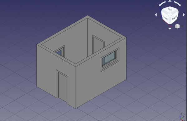
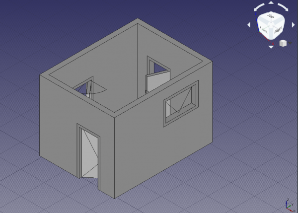
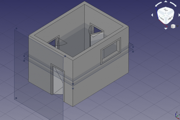
Wall built with doors and windows
Note: when placing a window or a door with a preset, hover the element over the Arch Wall, and wait for the element to rotate so that it is parallel to that wall. Aim for the bottom edge of the wall, and use the Sill height to adjust the distance from the floor. If this is difficult, use the Draft Near snapping mode of the Draft Snap toolbar to insert the element anywhere on the face of the wall, and then adjust its DataPosition manually as described above. Having many Draft Snap modes active at the same time may cause issues with placing the element, so try with only one option at a time.
Note 2: occasionally the window may be placed outside the Arch Wall; as long as the element is parallel to that wall, you should be able to correct the position manually.
Opening the doors
10. In the tree view select Sketch underlying Door, and press Space, or change the property ViewVisibility to true
11. Double click Door in the tree view to start editing it.
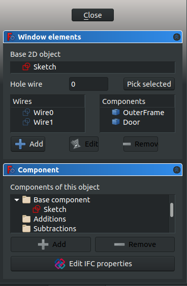
- 11.1. Inside the
Window elementsframe there are two panes,WiresandComponents. - Note: with a simple door preset there are two wires,
Wire0andWire1, and two components,OuterFrameandDoor. A custom designed Arch Door may have more wires and components.
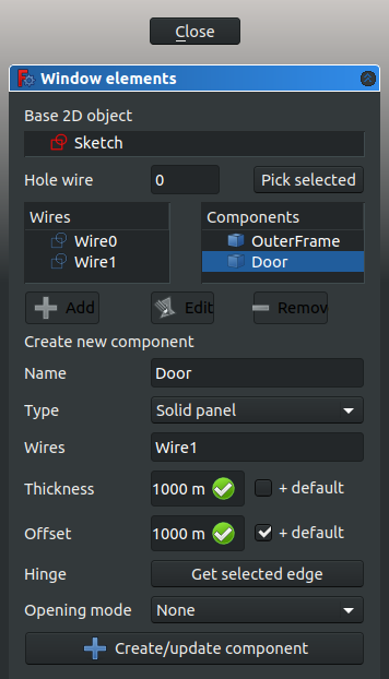
- 11.2. Click on
Door, and click the Edit button. This shows the properties of theDoorcomponent likeName,Type,Wires,Thickness,Offset,Hinge, andOpening mode. - 11.3. In the 3D view, select only one vertical edge in the visible sketch of the door, then click the Get selected edge button. The button should change to an edge name, for example, Edge8.
- 11.4. Change the
Opening modeto Arc 90, or any other option. - 11.5. Click the +Create/update component button, and then Close to finish editing the door. The sketch may become hidden again.
Dialog to edit a window or a door
Dialog to edit the components that make a window or a door
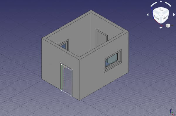
Vertical edge of sketch selected as hinge for a door
12. Select Door, and give the property DataOpening a value of 45. The solid panel of the door should open to the inside of the building.
13. Select Door, and change the property DataSymbol Elevation to true; the tip of the created wire indicates which side of the door opens; this is easier to see if the viewport changes to front view. Change the property DataSymbol Plan to true; a circular arc should indicate the extent of the door's swing; this is easier to see if the viewport changes to top view.
14. Repeat the steps with Door001 and the underlying Sketch001 to make the door open 75 degrees to the inside of the building. Also enable the elevation and plan symbols.
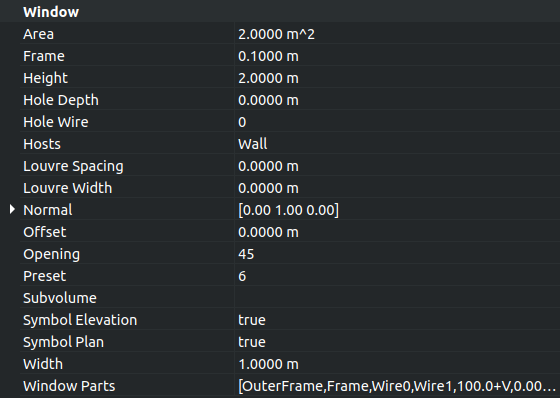
Property view of the door to change Opening value, Symbol elevation, Symbol plan, and other options
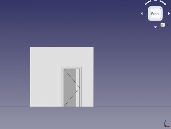
Door with opening elevation symbol, front view
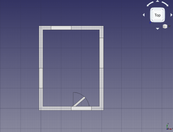
Door with plan symbol, top view
Opening the windows
15. In the tree view select Sketch002 underlying Window, and press Space, or change the property ViewVisibility to true.
16. Double click Window in the tree view to start editing it.
- 16.1. Click on the
InnerFramecomponent, and click the Edit button.
- 16.2. In the 3D view, select only one vertical edge of
Sketch002. The wires representingOuterFrameand theInnerFrameare very close to each other, so zoom in as close as possible to the sketch to select the appropriate wire. Then click the Get selected edge button. The button should change to an edge name, for example, Edge12. - Note: when there are many solids on the screen that it becomes difficult to select only one edge, switch to wireframe mode to remove the faces of those solid objects, and see only the wires, edges, and contours.
- 16.3. Change the
Opening modetoArc 90 inv, or any other option.
17. Select Window, and give the property DataOpening a value of 45. The inner frame containing the transparent glass should open to the inside of the building.
18. Select Window, and change the property DataSymbol Elevation to true; the tip of the created wire indicates which side of the window opens; this is easier to see if the viewport changes to left side view. Change the property DataSymbol Plan to true; a circular arc should indicate the extent of the window's swing; this is easier to see if the viewport changes to top view.
19. Repeat the steps with Window001 and the underlying Sketch003 to make the window open 75 degrees. Also show the elevation and plan symbols. In this case, don't pick a vertical wire of the InnerFrame as hinge, but pick the top horizontal wire. This means that this window will open differently from the other window. The elevation symbol will be better seen from a right side view. The plan symbol will be better seen from the front view; however, since the wall is obstructing the view, you can change its ViewTransparency to a value such as 85 to see through it; alternatively you can also change its ViewDisplay Mode to Wireframe to show only its edges.
Horizontal edge of sketch selected as hinge for a window
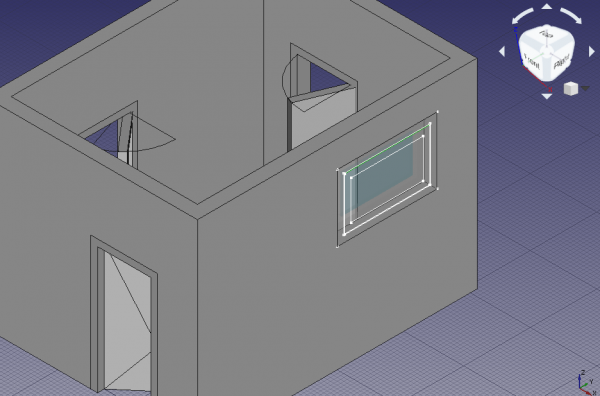
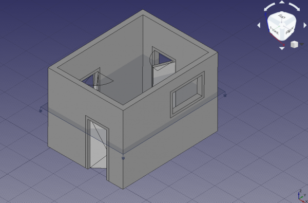
Elevation and plan symbols for all elements, axonometric view
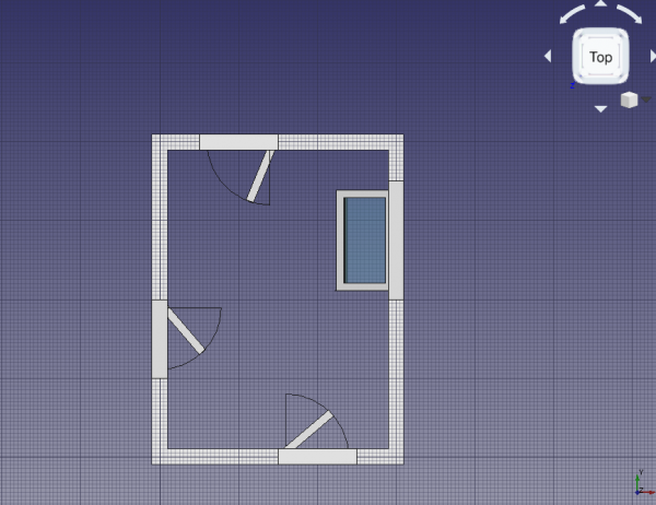
Elevation and plan symbols for all elements, top view
Making a floor plan of the building
20. Still in the Arch Workbench, select all components in the tree view, the Arch Wall, the two Arch Windows, and the two Arch Doors, then use the Arch SectionPlane tool to create a Section element.
Note: change the property DataArrow size of the section plane to a larger value, for example, 200 mm, so that the direction of the section is clearly visible in the 3D viewport.
Section plane cutting through solid objects, including walls, doors, and windows
21. Change to the TechDraw Workbench and insert a new page with the TechDraw PageDefault tool; a new Page object is created, and the view switches to this page. The page inserted is a standard A4 sheet in landscape orientation, with a basic frame around it. Use the TechDraw PageTemplate tool if you need to create a new page using a particular SVG template.
22. Select Section, and use the TechDraw ArchView tool to create an ArchView object in the page. Most probably the new object won't be visible in the page because it has a very large scale of 1, that is, 1:1. This means that every meter in the 3D view is shown as a meter in the page view; since the page is only 0.297 m x 0.210 m in size, most features are too big to fit in this page at their natural scale.
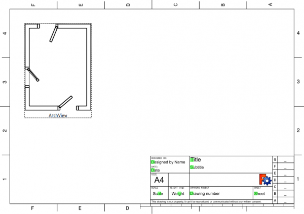
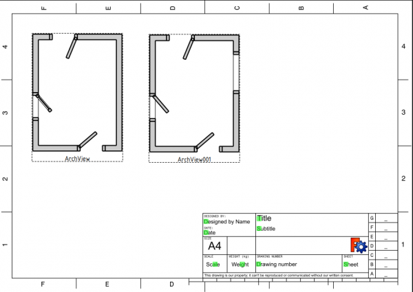
23. Select this ArchView object, and change the property DataScale to 0.02, which is equivalent to 1:50, a scale suitable for typical buildings. This means every meter in the 3D view will be shown as 20 mm in the page. The object should appear in the center of the page, and can be moved to a better position on the left side. The two doors should look like they are open, but only the left window should look open. The reason the right window doesn't appear in the projection is that the plane defined by Section does not cut through this right window.
Section plane cutting through solid objects, including walls, doors, and windows
24. Switch back to the Arch Workbench. In the tree view select all components again, and use the Arch SectionPlane tool to create a second Section001 element.
- 24.1. Select
Section001and change the property DataPosition to[1.5 m, 2.0 m, 1.8 m]. This second plane does cut through all Arch objects. - 24.2. Switch back to the TechDraw Workbench. Select
Section001, use the TechDraw ArchView tool to createArchView001, and set DataScale to0.02. The new view in the TechDraw page now shows all openings in the Arch Wall produced by doors and windows.
Note: set DataAll On to true for TechDraw ArchView objects so that all elements cut by the plane are visible in the page, regardless of their visibility state in the 3D viewport. The option DataShow Fill can also be set to true to draw a shade on the solids that were cut by the section plane.
Section view of the building, with a second plane cut, A4 sheet, scale 1:50
Making an elevation projection of the building
25. Go back to the Arch Workbench. In the tree view, select all components, the Arch Wall, the two Arch Windows, and the two Arch Doors, then use the Arch SectionPlane tool to create a third Section002 element.
- 25.1. Rotate
Section002, so that it cuts vertically through the building. Change the properties DataAxis to[1, 0, 0], and DataAngle to90. - 25.2. Change the DataPosition to
[1.5 m, -1 m, 1.5 m], so that the plane is in front of the building.
Section planes that cut or look at the building and the solid objects
26. Go back to the TechDraw Workbench, and use the TechDraw ArchView tool on Section002; remember to adjust the scale to 0.02 (1:50). Change DataRotation to -90 to correct the appearance of the projections. Arrange ArchView002 next to the other views in the page. This third projection looks at the building from the front.
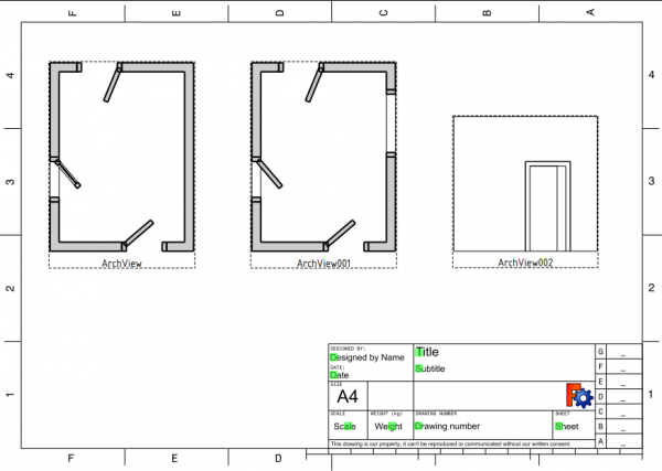
Section view of the building, two top views, and one elevation view, A4 sheet, scale 1:50
Arch and TechDraw interaction
As of the time of writing of this document (FreeCAD 0.18, November 2018), the TechDraw Workbench can only display in its pages what the Arch Workbench exports as SVG. This means that the appearance of the elements included within the Arch SectionPlane tool, and displayed by the TechDraw ArchView tool, is controlled by the Arch Workbench.
The TechDraw Workbench only has minimal control over how it displays those Arch SectionPlane (ArchView) objects. Therefore, bug reports and feature requests related to displaying Arch elements should be filed with both workbenches.
A closer interaction between the workbenches is planed for future versions of FreeCAD. In those versions it is expected that long-standing issues be resolved, such as controlling the characteristics of lines and faces (line width, line color, face color, hatch patterns, and others).
- 2D drafting: Sketch, Line, Polyline, Circle, Arc, Arc by 3 points, Fillet, Ellipse, Polygon, Rectangle, B-spline, Bézier curve, Cubic Bézier curve, Point
- 3D/BIM: Project, Site, Building, Level, Space, Wall, Curtain Wall, Column, Beam, Slab, Door, Window, Pipe, Pipe Connector, Stairs, Roof, Panel, Frame, Fence, Truss, Equipment
- Reinforcement tools: Custom Rebar, Straight Rebar, U-Shape Rebar, L-Shape Rebar, Stirrup, Bent-Shape Rebar, Helical Rebar, Column Reinforcement, Beam Reinforcement, Slab Reinforcement, Footing Reinforcement
- Generic 3D tools: Profile, Box, Shape builder..., Facebinder, Objects library, Component, External reference
- Annotation: Text, Shape from text, Aligned dimension, Horizontal dimension, Vertical dimension, Leader, Label, Axis, Axes System, Grid, Section Plane, Hatch, Page, View, Shape-based view
- Snapping: Snap lock, Snap endpoint, Snap midpoint, Snap center, Snap angle, Snap intersection, Snap perpendicular, Snap extension, Snap parallel, Snap special, Snap near, Snap ortho, Snap grid, Snap working plane, Snap dimensions, Toggle grid, Working Plane Top, Working Plane Front, Working Plane Side
- Modify: Move, Copy, Rotate, Clone, Create simple copy, Make compound, Offset, 2D Offset..., Trimex, Join, Split, Scale, Stretch, Draft to sketch, Upgrade, Downgrade, Add component, Remove component, Array, Path array, Polar array, Point array, Cut with plane, Mirror, Extrude..., Difference, Union, Intersection
- Manage: BIM Setup..., Views manager, Manage project..., Manage doors and windows..., Manage IFC elements..., Manage IFC quantities..., Manage IFC properties..., Manage classification..., Manage layers..., Material, Schedule, Preflight checks..., Annotation styles...
- Utils: Toggle bottom panels, Move to Trash, Working Plane View, Select group, Set slope, Create working plane proxy, Add to construction group, Split Mesh, Mesh to Shape, Select non-manifold meshes, Remove Shape from Arch, Close Holes, Merge Walls, Check, Toggle IFC Brep flag, Toggle subcomponents, Survey, IFC Diff, IFC explorer, Create IFC spreadsheet..., Image plane, Unclone, Rewire, Glue, Reextrude
- Panel tools: Panel, Panel Cut, Panel Sheet, Nest
- Structure tools: Structure, Structural System, Multiple Structures
- IFC tools: IFC Diff..., IFC Expand, Make IFC project, IfcOpenShell update
- Nudge: Nudge Switch, Nudge Up, Nudge Down, Nudge Left, Nudge Right, Nudge Rotate Left, Nudge Rotate Right, Nudge Extend, Nudge Shrink
- Additional: Preferences, Fine tuning, Import Export Preferences, IFC, DAE, OBJ, JSON, 3DS, SHP
- Drafting: Line, Polyline, Fillet, Arc, Arc by 3 points, Circle, Ellipse, Rectangle, Polygon, B-spline, Cubic Bézier curve, Bézier curve, Point, Facebinder, ShapeString, Hatch
- Annotation: Text, Dimension, Label, Annotation styles, Annotation scale
- Modification: Move, Rotate, Scale, Mirror, Offset, Trimex, Stretch, Clone, Array, Polar array, Circular array, Path array, Path link array, Point array, Point link array, Edit, Subelement highlight, Join, Split, Upgrade, Downgrade, Wire to B-spline, Draft to sketch, Set slope, Flip dimension, Shape 2D view
- Draft Tray: Select plane, Set style, Toggle construction mode, AutoGroup
- Snapping: Snap lock, Snap endpoint, Snap midpoint, Snap center, Snap angle, Snap intersection, Snap perpendicular, Snap extension, Snap parallel, Snap special, Snap near, Snap ortho, Snap grid, Snap working plane, Snap dimensions, Toggle grid
- Miscellaneous: Apply current style, Layer, Manage layers, Add a new named group, Move to group, Select group, Add to construction group, Toggle normal/wireframe display, Create working plane proxy, Heal, Show snap toolbar
- Additional: Constraining, Pattern, Preferences, Import Export Preferences, DXF/DWG, SVG, OCA, DAT
- Context menu:
- Layer container: Merge layer duplicates, Add new layer
- Layer: Activate this layer, Select layer contents
- Text: Open hyperlinks
- Wire: Flatten
- Working plane proxy: Write camera position, Write objects state
- Pages: Insert Default Page, Insert Page using Template, Update template fields, Redraw Page, Print All Pages, Export Page as SVG, Export Page as DXF
- Views:
- TechDraw views: Insert View, Insert Broken View, Insert Section View, Insert Complex Section View, Insert Detail View, Insert Projection Group, Insert Clip Group, Insert SVG Symbol, Insert Bitmap Image, Share View, Turn View Frames On/Off, Project Shape
- Views from other workbenches: Insert Active View, Insert Draft Workbench Object, Insert BIM Workbench Object, Insert Spreadsheet View
- Stacking: Move view to top of stack, Move view to bottom of stack, Move view up one level, Move view down one level
- Dimensions: Insert Dimension, Insert Length Dimension, Insert Horizontal Dimension, Insert Vertical Dimension, Insert Radius Dimension, Insert Diameter Dimension, Insert Angle Dimension, Insert 3-Point Angle Dimension, Insert Area Annotation, Create Arc Length Dimension, Insert Horizontal Extent Dimension, Insert Vertical Extent Dimension, Create Horizontal Chain Dimensions, Create Vertical Chain Dimensions, Create Oblique Chain Dimensions, Create Horizontal Coordinate Dimensions, Create Vertical Coordinate Dimensions, Create Oblique Coordinate Dimensions, Create Horizontal Chamfer Dimension, Create Vertical Chamfer Dimension, Insert Balloon Annotation, Insert Axonometric Length Dimension, Insert Landmark Dimension, Dimension Repair, Link Dimension to 3D Geometry
- Hatching: Hatch Face using Image File, Apply Geometric Hatch to Face,
- Annotations: Insert Annotation, Add Leaderline to View, Insert Rich Text Annotation, Add Cosmetic Vertex, Add Midpoint Vertices, Add Quadrant Vertices, Add Centerline to Faces, Add Centerline between 2 Lines, Add Centerline between 2 Points, Add Cosmetic Line Through 2 points, Add Cosmetic Circle, Change Appearance of Lines, Show/Hide Invisible Edges, Add Welding Information to Leader, Add Surface Finish Symbol, Add Hole or Shaft Tolerances
- Extensions:
- Attributes and modifications: Select Line Attributes, Cascade Spacing and Delta Distance, Change Line Attributes, Extend Line, Shorten Line, Lock/Unlock View, Position Section View, Position Horizontal Chain Dimensions, Position Vertical Chain Dimensions, Position Oblique Chain Dimensions, Cascade Horizontal Dimensions, Cascade Vertical Dimensions, Cascade Oblique Dimensions, Calculate the area of selected faces, Calculate the arc length of selected edges, Customize format label
- Centerlines and threading: Add Circle Centerlines, Add Bolt Circle Centerlines, Add Cosmetic Thread Hole Side View, Add Cosmetic Thread Hole Bottom View, Add Cosmetic Thread Bolt Side View, Add Cosmetic Thread Bolt Bottom View, Add Cosmetic Intersection Vertex(es), Add an offset vertex, Add Cosmetic Circle, Add Cosmetic Arc, Add Cosmetic Circle 3 Points, Add Cosmetic Parallel Line, Add Cosmetic Perpendicular Line
- Dimensions: Insert '⌀' Prefix, Insert '□' Prefix, Insert 'n×' Prefix, Remove Prefix, Increase Decimal Places, Decrease Decimal Places
- Miscellaneous: Remove Cosmetic Object
- Additional: Line Groups, Templates, Hatching, Geometric dimensioning and tolerancing, Preferences
- Getting started
- Installation: Download, Windows, Linux, Mac, Additional components, Docker, AppImage, Ubuntu Snap
- Basics: About FreeCAD, Interface, Mouse navigation, Selection methods, Object name, Preferences, Workbenches, Document structure, Properties, Help FreeCAD, Donate
- Help: Tutorials, Video tutorials
- Workbenches: Std Base, Assembly, BIM, CAM, Draft, FEM, Inspection, Material, Mesh, OpenSCAD, Part, PartDesign, Points, Reverse Engineering, Robot, Sketcher, Spreadsheet, Surface, TechDraw, Test Framework
- Hubs: User hub, Power users hub, Developer hub