
Tutorial custom placing of windows and doors
| Topic |
|---|
| Architecture |
| Level |
| Intermediate |
| Time to complete |
| 60 minutes |
| Authors |
| vocx |
| FreeCAD version |
| 0.18 or greater |
| Example files |
| none |
| See also |
| None |
Introduction
This tutorial shows how to place custom designed Arch Windows and Arch Doors in a building model. It uses the Draft Workbench, the Arch Workbench, and the Sketcher Workbench.
Common tools used are: Draft Grid, Draft Snap, Draft Wire, Arch Wall, Arch Window, and Sketcher NewSketch. The user should be familiar with constraining sketches.
This tutorial was inspired by the tutorials by jpg87 posted in the FreeCAD forums.
See also the following thread for more information on the position of windows and doors.
See also the following page for some videos on how to align windows.
Setup
1. Open FreeCAD, create a new empty document, and switch to the Arch Workbench.
2. Make sure your units are set correctly in the menu Edit → Preferences → General → Units. For example, MKS (m/kg/s/degree) is good for dealing with distances in a typical building; moreover, set the number of decimals to 4, to consider even the smallest fractions of a meter.
3. Use the Draft ToggleGrid button to show a grid with enough resolution. You can change the grid appearance in the menu Edit → Preferences → Draft → Grid and snapping → Grid. Set lines at every 50 mm, with major lines every 20 lines (every meter), and 1000 lines in total (the grid covers an area of 50 m x 50 m).
4. Zoom out of the 3D view if you are too close to the grid.
Now we are ready to create a simple wall on which we can position windows and doors.
Placing a wall
5. Use the Draft Wire tool to create a wire. Go counterclockwise.
- 5.1. First point in (0, 4, 0); in the dialog enter 0 m Enter, 4 m Enter, 0 m Enter.
- 5.2. Second point in (2, 0, 0); in the dialog enter 2 m Enter, 0 m Enter, 0 m Enter.
- 5.3. Third point in (4, 0, 0); in the dialog enter 4 m Enter, 0 m Enter, 0 m Enter.
- 5.4. Fourth point in (6, 2, 0); in the dialog enter 6 m Enter, 2 m Enter, 0 m Enter.
- 5.4. Fifth point in (6, 5, 0); in the dialog enter 6 m Enter, 5 m Enter, 0 m Enter.
- 5.5. In the number pad press A to finish the wire.
- 5.6. In the number pad press 0 to get an axonometric view of the model.
- Note: make sure the Relative checkbox is disabled if you are giving absolute coordinates.
- Note 2: the points can also be defined with the mouse pointer by choosing intersections on the grid, with the help of the Draft Snap toolbar and the Draft Grid method.
- Note 3: you can also create shapes programmatically by scripting in Python. Beware that most functions expect their input in millimeters.
import FreeCAD
import Draft

p = [FreeCAD.Vector(0.0, 4000.0, 0),
FreeCAD.Vector(2000.0, 0.0, 0.0),
FreeCAD.Vector(4000.0, 0.0, 0.0),
FreeCAD.Vector(6000.0, 2000.0, 0.0),
FreeCAD.Vector(6000.0, 5000.0, 0.0)]

w = Draft.makeWire(p, closed=False)
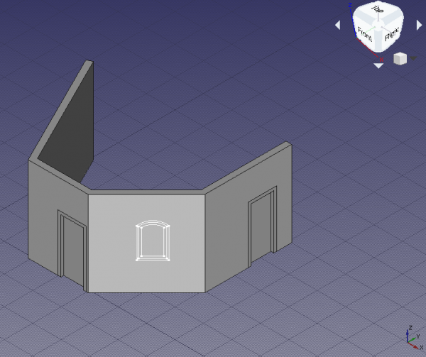
6. Select the DWire and click the Arch Wall tool; the wall is immediately created with a default width (thickness) of 0.2 m, and height of 3 m.
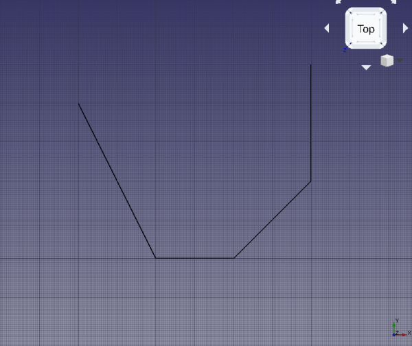
Base wire for the wall
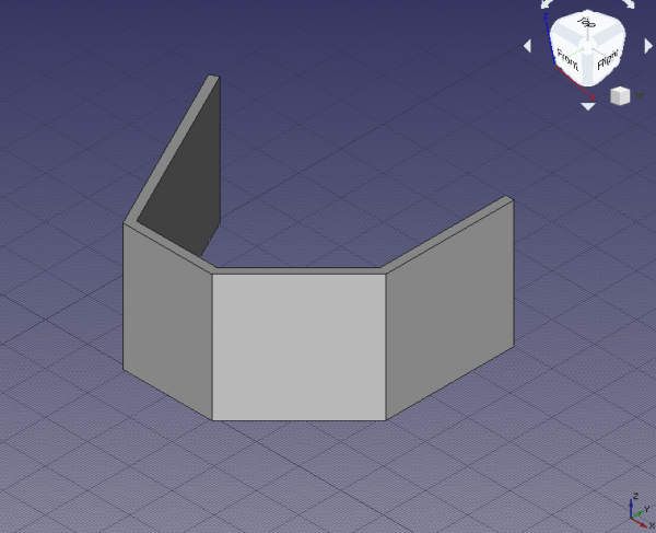
Wall constructed from the wire
Placing preset doors and windows
7. Click the Arch Window tool; as preset select Simple door, and change the height to 2 m.
- 7.1. Change the snapping to Draft Midpoint, and try selecting the bottom edge of the frontal wall; rotate the standard view as necessary to help you pick the edge and not the wall face; when the midpoint is active, click to place the door.
- 7.2. Click the Arch Window tool again, and place another door, but this time in the midpoint of the rightmost wall; rotate the standard view as necessary.
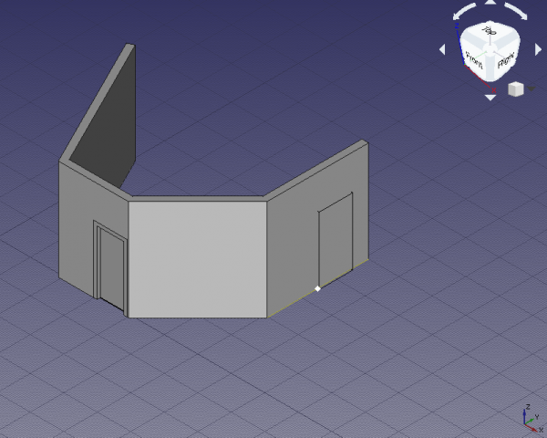
Snapping to the midpoint of the bottom edge of the wall to place the door
- Note: the
Sill heightis the distance from the floor to the lower edge of the element. For doors theSill heightis usually 0 m as doors are normally touching the floor; on the other hand, windows have a usual separation of 0.5 m to 1.5 m from the floor. TheSill heightcan only be set when initially creating the window or door from a preset. Once the window or door is inserted, modify its placement by editing the DataPosition vector[x, y, z]of the underlying Sketcher Sketch.
Creating custom doors and windows
8. Switch to the Sketcher Workbench; select the part of the wall to the right that has no door; click on the Sketcher NewSketch; select FlatFace as attachment method. If the existing geometry obstructs your view, click on Sketcher ViewSection to remove it.
9. Draw a fancy sketch containing three closed wires. Make sure to provide constraints to all wires.
- 9.1. The outside wire is the biggest one, and will define the main dimensions of the window object, and the size of the hole created when it's embedded in an Arch Wall. Make sure the dimensions are named appropriately, for example,
WidthandHeight. A constraint also defines the curvature of the outer wire; give it an appropriate name, likeHeightCurve. - 9.2. The second wire is offset from the outer wire, and together with it, they define the width of the fixed frame of the window. Name the offset appropriately, for example,
FrameFixedOffset. It will be used for both the top vertical and horizontal offsets. The bottom offset, if set to zero, will result in the fixed frame touching the bottom of the window; this can be used to model a door instead of a window. Give it an appropriate name, likeFrameFixedBottom. - 9.3. The third, innermost wire is offset from the second wire, and together with it, they define the frame of the window that can open. The innermost wire also defines the size of the glass panel. Again, give meaningful names to these offsets, for example,
FrameInnerOffsetandFrameInnerBottom. - 9.4. In order to build succesfully the sketch, use horizontal (Sketcher ConstrainHorizontal) and vertical (Sketcher ConstrainVertical) constraints for the straight sides; use auxiliary construction geometry (Sketcher ToggleConstruction), and tangential constraints (Sketcher ConstrainTangent) to correctly place the circular arcs at the top. As in this case the window is symmetrical, consider equality (Sketcher ConstrainEqual), symmetrical (Sketcher ConstrainSymmetric), and point on object (Sketcher ConstrainPointOnObject) constraints where it makes sense.
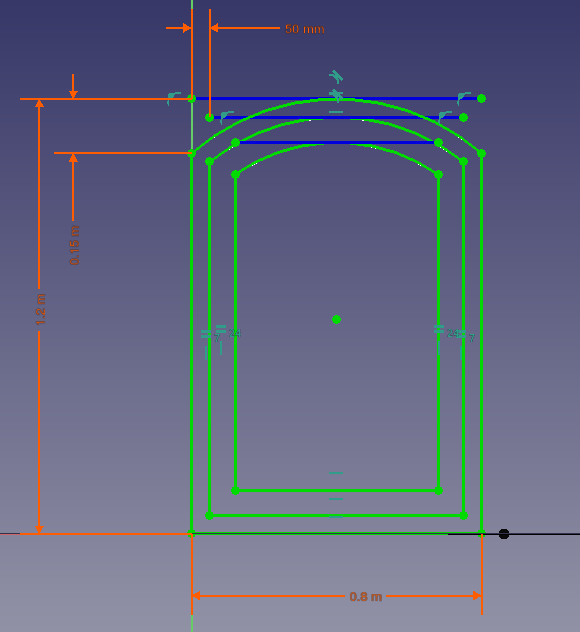
Constraints for the outer wires of the sketch that form the window
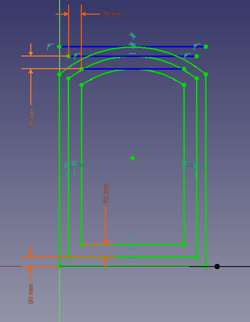
Constraints for the inner wires of the sketch that form the window
10. Once the sketch is fully constrained, press Close to exit the sketch (Sketcher LeaveSketch).
- 10.1. Since a face of the wall was selected during the initial step of creating the sketch, the sketch is co-planar with that face; however, it may be in the wrong position, away from the wall. If this is the case, adjust DataPosition within DataAttachment Offset. Set DataPosition to
[4 m, 1 m, 0 m]so the sketch is centered in the wall, and it is one meter above the floor level. - 10.2. You can see the named constraints under DataConstraints. The values can be modified to see the sketch change dimensions immediately.
Window sketch moved to the desired position on the wall
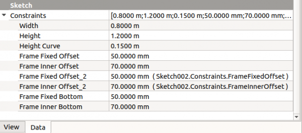
Named constraints of the sketch, which can be modified without going inside the sketch
11. Change back to the Arch Workbench and, with the new Sketch002 selected, use Arch Window. A window will be created, and will make a hole in the wall. The window is made from a custom sketch, and not from a preset, so it needs to be edited in order to correctly display its components, that is, the fixed frame, the inner frame, and the glass panel.
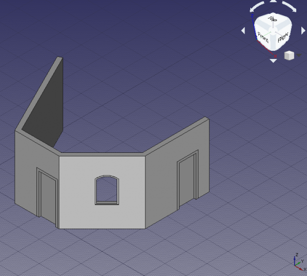
Custom window created from the sketch; it still doesn't have a proper frame, nor glass
Setting up the custom window
12. In the tree view select Sketch002 underlying Window, and press Space, or change the property ViewVisibility to true.
13. Double click Window in the tree view to start editing it.
- 13.1. Inside the
Window elementsdialog there are two panes,WiresandComponents. There are three wires,Wire0,Wire1, andWire2, and one component,Default. The wires refer to the closed loops that were drawn in the sketch; the components define the areas in the sketch that will be extruded to create frame or glass panels with real thicknesses; these areas are delimited by the wires. A window created from a preset already has two components,OuterFrameandGlass. The custom window needs to be edited to have a similar structure.
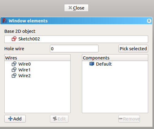
Dialog to edit a window or a door
- 13.2. Click on
Default, and click the Remove button to eliminate it.
- 13.3. Click Add; this shows the properties of a new component like
Name,Type,Wires,Thickness,Offset,Hinge, andOpening mode. Give a name, such asOuterFrame, chooseFrameforType, and click onWire0and thenWire1; they should highlight in the 3D viewport. Add a small value forThickness,15 mm, and check the checkbox to add the default value. This default value is the length assigned to the DataFrame property; a similar default can be assigned to the DataOffset property. Click the +Create/update component button to finish editing the component.
- 13.4. Click Add; give another name, such as
InnerFrame, chooseFrameforType, and click onWire1and thenWire2. Add a sensibleThickness,60 mm, andOffset,15 mm. Then click the +Create/update component button.
- 13.5. Click Add; give another name, such as
Glass, chooseGlass panelforType, and click onWire2. Add a sensibleThickness,10 mm, andOffset,40 mm. Then click the +Create/update component button. If any of the three components needs to be modified, select it and press Edit; modifications are only saved after pressing the +Create/update component button.
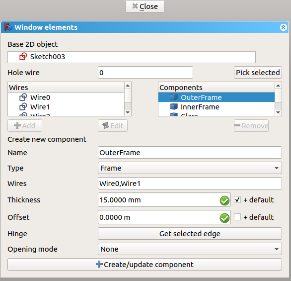
Editing a previously defined component of a window or a door
- 13.6. If everything is set, click Close to finish editing the window. The sketch may become hidden again, but the window will show distinct solid elements for the
OuterFrame, theInnerFrame, and theGlass. Give a value of100 mmto DataFrame to assign a default thickness, which will be added to the value specified in theOuterFramecomponent.
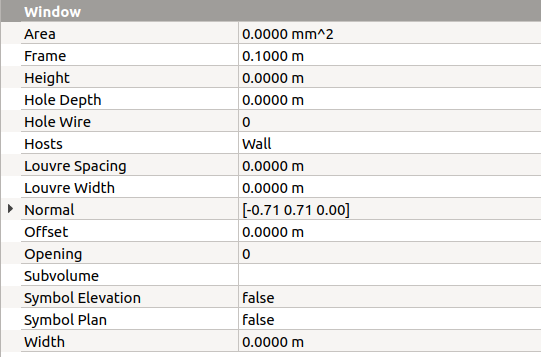
Property view of the window to add default Frame length, Offset length, and other options
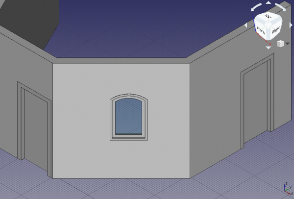
Finished window with appropriate components embedded in the wall
Duplicating the custom window
14. In the tree view, select Window and its underlying Sketch002. Then go to Edit → Duplicate selection, and answer No if asked to duplicate unselected dependencies. A new Window001 and Sketch003 will appear in the same position as the original elements.
15. Select the new Sketch003. Go to the DataMap Mode property, and click on the ellipsis next to the FlatFace value. In the 3D viewport select the left side of the wall which doesn't have any element; rotate the standard view as necessary. Change the Attachment offset to [-1 m, 0 m, 0 m] to center the window, and click OK. The sketch and the window should appear in a new position.
- Note: the attachment operation can also be performed by changing to the Part Workbench, and then using the menu Part → Attachment.
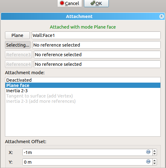
Dialog to edit the attachment plane of the sketch
16. You may adjust the dimensions of the new window by changing the named parameters in Sketch003 under DataConstraints, for example, set Height to 2 m, and Frame Fixed Bottom to 0 m. Then press Ctrl+R to recompute the model. If the wall doesn't show a bigger hole for the new window, select the wall in the tree view, right click and choose Mark to recompute, then press Ctrl+R again.
17. These operations have changed the position of the new window, but the opening in the wall doesn't look correct. It is slanted, that is, the hole is not perpendicular to the face of the wall, and it may even cut other parts of the wall. The problem is that Window001 has retained the DataNormal information of the original Window.
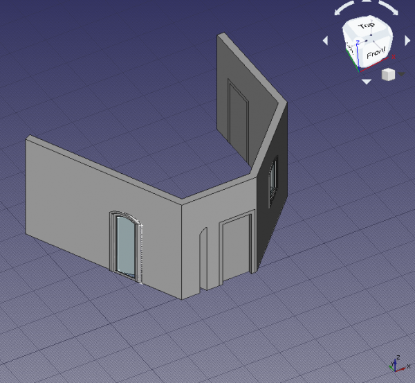
Incorrect opening in the wall due to bad Normal of the window
Normals of doors and windows
18. Each Arch Window object controls the extrusion of its body and the opening that is created in its host wall by means of the DataNormal.
The normal is a vector [x, y, z] that indicates a direction perpedicular to a wall. When a window or door preset is created with the Arch Window tool directly over an Arch Wall, the normal is automatically calculated, and the resulting window or door is correctly aligned; the first two objects, Door and Door001, were created in this way.
In similar way, when a sketch is created by selecting a planar surface, it is oriented on this plane. Then when the Arch Window tool is used, the window will use as normal the perpendicular direction to the sketch. This was the case with the third object, the custom Window.
If the window already exists and needs to be moved, as was the case with the duplicated Window001 object, the sketch needs to be remapped to another plane; doing this moves both the sketch and the window, but the latter doesn't automatically update its normal, so it has incorrect extrusion information. The normal needs to be calculated manually and written to DataNormal.
The three values of the normal vector are calculated as following.
x = -sin(angle)
y = cos(angle)
z = 0
Where angle is the angle of the local Z axis of the sketch with respect to the global Y axis.
When a sketch is created, it always has two axes, a local X (red) and a local Y (green). If the sketch is mapped to the global XY working plane, then these axes are aligned; but if the sketch is mapped on the global XZ or global YZ planes, as is common with windows and doors (the sketches are "standing up"), then the local Z (blue) forms an angle with the global Y axis; this angle varies from -180 to 180 degrees. The angle is considered positive if it opens counterclockwise, and it is negative if it opens clockwise, starting from the global Y axis.
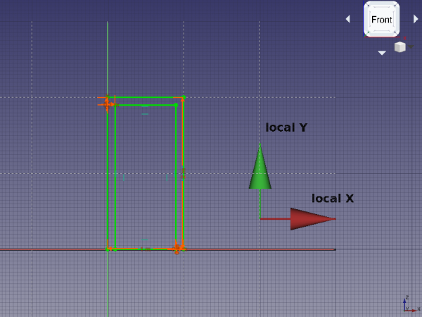
Local coordinates of a sketch that is "standing up", that is, mapped to the global XZ plane
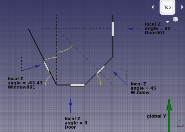
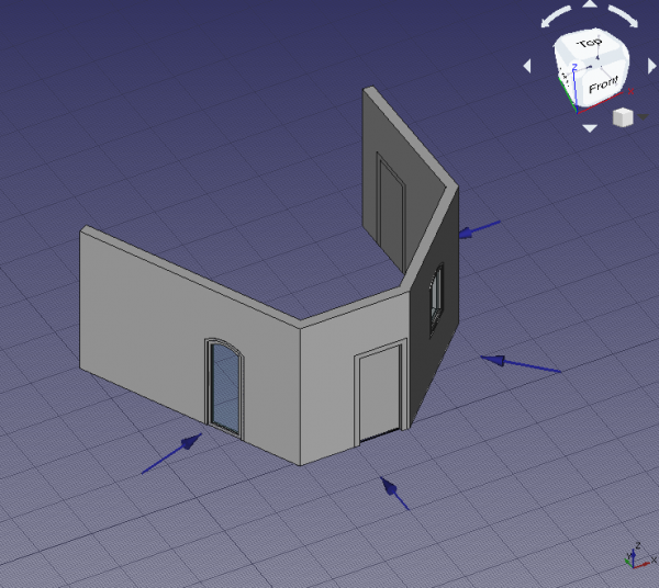
Intended directions of the normals for each door and window
If we look at the geometry created so far, we see the following normals.
Door- The local Z is aligned with the global Y, therefore, the
angleis zero. The normal vector is
x = -sin(0) = 0
y = cos(0) = 1
z = 0
or DataNormal is [0, 1, 0].
Door001- The local Z is rotated 90 degrees from the global Y, therefore, the
angleis 90 (positive, because it opens counterclockwise). The normal vector is
x = -sin(90) = -1
y = cos(90) = 0
z = 0
or DataNormal is [-1, 0, 0].
Window- The local Z is rotated 45 degrees from the global Y, therefore, the
angleis 45 (positive, because it opens counterclockwise). The normal vector is
x = -sin(45) = -0.7071
y = cos(45) = 0.7071
z = 0
or DataNormal is [-0.7071, 0.7071, 0].
Window001- The local Z direction is found by using the Draft Dimension tool and measuring the angle that the wall trace (
Wire) makes with the global Y axis, or any line aligned to it. This angle is26.57; the desired angle is the complement to this, so90 - 26.57 = 63.43.
This means the local Z axis is rotated 63.43 degrees from the global Y, therefore, the angle is -63.46 (negative, because it opens clockwise). The normal vector is
x = -sin(-63.43) = 0.8943
y = cos(-63.43) = 0.4472
z = 0
Therefore DataNormal should be changed to [0.8943, 0.4472, 0].
After doing these changes, recompute the model with Ctrl+R. If the wall doesn't update the hole, select it in the tree view, right click and choose Mark to recompute, then press Ctrl+R again.
19. The orientation of the extrusion of the window is resolved, together with the opening in the wall.
Correct opening in the wall due to proper Normal of the window
Final remarks
20. As demonstrated, the initial placement of the Arch Window is very important. The user should either
- use the Arch Window tool to insert and automatically align a preset to a wall, or
- map a sketch to the desired wall, and build the window after that.
If a window already exists, and it needs to be moved, the supporting sketch should be remapped to a new plane, and the DataNormal of the window needs to be recalculated.
The new normal direction can be obtained by measuring the angle of the new wall with respect to the global Y axis, considering whether this angle is positive (counterclockwise) or negative (clockwise), and using a simple formula.
x = -sin(angle)
y = cos(angle)
z = 0
To confirm that the operations are correct, the absolute magnitude of the normal vector should be one. That is,
abs(N) = 1 = sqrt(x^2 + y^2 + z^2)
abs(N) = 1 = sqrt(sin^2(angle) + cos^2(angle) + z^2)
- 2D drafting: Sketch, Line, Polyline, Circle, Arc, Arc by 3 points, Fillet, Ellipse, Polygon, Rectangle, B-spline, Bézier curve, Cubic Bézier curve, Point
- 3D/BIM: Project, Site, Building, Level, Space, Wall, Curtain Wall, Column, Beam, Slab, Door, Window, Pipe, Pipe Connector, Stairs, Roof, Panel, Frame, Fence, Truss, Equipment
- Reinforcement tools: Custom Rebar, Straight Rebar, U-Shape Rebar, L-Shape Rebar, Stirrup, Bent-Shape Rebar, Helical Rebar, Column Reinforcement, Beam Reinforcement, Slab Reinforcement, Footing Reinforcement
- Generic 3D tools: Profile, Box, Shape builder..., Facebinder, Objects library, Component, External reference
- Annotation: Text, Shape from text, Aligned dimension, Horizontal dimension, Vertical dimension, Leader, Label, Axis, Axes System, Grid, Section Plane, Hatch, Page, View, Shape-based view
- Snapping: Snap lock, Snap endpoint, Snap midpoint, Snap center, Snap angle, Snap intersection, Snap perpendicular, Snap extension, Snap parallel, Snap special, Snap near, Snap ortho, Snap grid, Snap working plane, Snap dimensions, Toggle grid, Working Plane Top, Working Plane Front, Working Plane Side
- Modify: Move, Copy, Rotate, Clone, Create simple copy, Make compound, Offset, 2D Offset..., Trimex, Join, Split, Scale, Stretch, Draft to sketch, Upgrade, Downgrade, Add component, Remove component, Array, Path array, Polar array, Point array, Cut with plane, Mirror, Extrude..., Difference, Union, Intersection
- Manage: BIM Setup..., Views manager, Manage project..., Manage doors and windows..., Manage IFC elements..., Manage IFC quantities..., Manage IFC properties..., Manage classification..., Manage layers..., Material, Schedule, Preflight checks..., Annotation styles...
- Utils: Toggle bottom panels, Move to Trash, Working Plane View, Select group, Set slope, Create working plane proxy, Add to construction group, Split Mesh, Mesh to Shape, Select non-manifold meshes, Remove Shape from Arch, Close Holes, Merge Walls, Check, Toggle IFC Brep flag, Toggle subcomponents, Survey, IFC Diff, IFC explorer, Create IFC spreadsheet..., Image plane, Unclone, Rewire, Glue, Reextrude
- Panel tools: Panel, Panel Cut, Panel Sheet, Nest
- Structure tools: Structure, Structural System, Multiple Structures
- IFC tools: IFC Diff..., IFC Expand, Make IFC project, IfcOpenShell update
- Nudge: Nudge Switch, Nudge Up, Nudge Down, Nudge Left, Nudge Right, Nudge Rotate Left, Nudge Rotate Right, Nudge Extend, Nudge Shrink
- Additional: Preferences, Fine tuning, Import Export Preferences, IFC, DAE, OBJ, JSON, 3DS, SHP
- Drafting: Line, Polyline, Fillet, Arc, Arc by 3 points, Circle, Ellipse, Rectangle, Polygon, B-spline, Cubic Bézier curve, Bézier curve, Point, Facebinder, ShapeString, Hatch
- Annotation: Text, Dimension, Label, Annotation styles, Annotation scale
- Modification: Move, Rotate, Scale, Mirror, Offset, Trimex, Stretch, Clone, Array, Polar array, Circular array, Path array, Path link array, Point array, Point link array, Edit, Subelement highlight, Join, Split, Upgrade, Downgrade, Wire to B-spline, Draft to sketch, Set slope, Flip dimension, Shape 2D view
- Draft Tray: Select plane, Set style, Toggle construction mode, AutoGroup
- Snapping: Snap lock, Snap endpoint, Snap midpoint, Snap center, Snap angle, Snap intersection, Snap perpendicular, Snap extension, Snap parallel, Snap special, Snap near, Snap ortho, Snap grid, Snap working plane, Snap dimensions, Toggle grid
- Miscellaneous: Apply current style, Layer, Manage layers, Add a new named group, Move to group, Select group, Add to construction group, Toggle normal/wireframe display, Create working plane proxy, Heal, Show snap toolbar
- Additional: Constraining, Pattern, Preferences, Import Export Preferences, DXF/DWG, SVG, OCA, DAT
- Context menu:
- Layer container: Merge layer duplicates, Add new layer
- Layer: Activate this layer, Select layer contents
- Text: Open hyperlinks
- Wire: Flatten
- Working plane proxy: Write camera position, Write objects state
- General: Create sketch, Edit sketch, Attach sketch, Reorient sketch, Validate sketch, Merge sketches, Mirror sketch, Leave sketch, View sketch, View section, Toggle grid, Toggle snap, Configure rendering order, Stop operation
- Sketcher geometries: Point, Polyline, Line, Arc, Arc by 3 points, Arc of ellipse, Arc of hyperbola, Arc of parabola, Circle, Circle by 3 points, Ellipse, Ellipse by 3 points, Rectangle, Centered rectangle, Rounded rectangle, Triangle, Square, Pentagon, Hexagon, Heptagon, Octagon, Regular polygon, Slot, Arc slot, B-spline by control points, Periodic B-spline by control points, B-spline by knots, Periodic B-spline by knots, Toggle construction geometry
- Sketcher constraints:
- Dimensional constraints: Dimension, Horizontal distance, Vertical distance, Distance, Auto radius/diameter, Radius, Diameter, Angle, Lock
- Geometric constraints: Coincident (unified), Coincident, Point on object, Horizontal/vertical, Horizontal, Vertical, Parallel, Perpendicular, Tangent or collinear, Equal, Symmetric, Block
- Other constraints: Refraction (Snell's law)
- Constraint tools: Toggle driving/reference constraint, Activate/deactivate constraint
- Sketcher tools: Fillet, Chamfer, Trim, Split, Extend, External geometry, Carbon copy, Select origin, Select horizontal axis, Select vertical axis, Array transform, Polar transform, Scale transform, Offset geometry, Symmetry, Remove axes alignment, Delete all geometry, Delete all constraints
- Sketcher B-spline tools: Convert geometry to B-spline, Increase B-spline degree, Decrease B-spline degree, Increase knot multiplicity, Decrease knot multiplicity, Insert knot, Join curves
- Sketcher visual: Select unconstrained DoF, Select associated constraints, Select associated geometry, Select redundant constraints, Select conflicting constraints, Show/hide circular helper for arcs, Show/hide B-spline degree, Show/hide B-spline control polygon, Show/hide B-spline curvature comb, Show/hide B-spline knot multiplicity, Show/hide B-spline control point weight, Show/hide internal geometry, Switch virtual space
- Additional: Sketcher Dialog, Preferences, Sketcher scripting
- Getting started
- Installation: Download, Windows, Linux, Mac, Additional components, Docker, AppImage, Ubuntu Snap
- Basics: About FreeCAD, Interface, Mouse navigation, Selection methods, Object name, Preferences, Workbenches, Document structure, Properties, Help FreeCAD, Donate
- Help: Tutorials, Video tutorials
- Workbenches: Std Base, Assembly, BIM, CAM, Draft, FEM, Inspection, Material, Mesh, OpenSCAD, Part, PartDesign, Points, Reverse Engineering, Robot, Sketcher, Spreadsheet, Surface, TechDraw, Test Framework
- Hubs: User hub, Power users hub, Developer hub