
Draft tutorial
| Topic |
|---|
| Drafting |
| Level |
| Beginner |
| Time to complete |
| 30 minutes |
| Authors |
| Drei and vocx |
| FreeCAD version |
| 0.19 |
| Example files |
| Draft tutorial updated |
| See also |
| None |
Introduction
This tutorial was originally written by Drei, and it was rewritten and illustrated by vocx.
This tutorial is meant to introduce the reader to the basic workflow of the ![]() Draft Workbench.
Draft Workbench.
The reader will practice:
- creation of lines, arcs, and polygons
- the use of working planes
- the creation of dimensions, text, and shapestrings
- the creation of a technical drawing
This tutorial uses the notation (x, y, z) to denote the coordinates required to define points in an object. The default unit is millimeters mm.
![]()
Final drawing including various Draft objects.
Setup
1. Open FreeCAD, create a new empty document with File → ![]() New.
New.
- 1.1. Switch to the Draft Workbench from the workbench selector, or the menu View → Workbench →
 Draft.
 - 1.2. Make sure you understand how to use the property editor, particularly the Data and View tabs to change the properties. When changing properties, you may have to do a
 Std Refresh action to see the result in the 3D view.
 - 1.3. Since the Draft objects are planar shapes, they are better viewed from the top. Use
 View top to set the 3D view.
 - 1.4. Although it is not used in this tutorial, the Draft grid is helpful to position geometrical elements. Use
 SelectPlane to set both the working plane and the grid, and then show and hide the grid with
  Toggle grid.
Snap toolbar
2. The Draft Snap toolbar is normally activated when you switch to the Draft Workbench.
- 2.1. To make sure it is always there, go to the Draft Preferences, Edit → Preferences → Draft → Grid and snapping tab.
- 2.2. Verify that the Show Draft Snap toolbar is active.
You can also change the visibility and properties of the Draft grid in this same window.
Working planes
Most Draft objects are planar shapes so they are naturally based on a working plane. A working plane can be one of the main XY, XZ, and YZ global coordinate planes, or it can be a plane that is parallel to them with a positive or negative offset, or it can be a plane defined by the face of a solid object.
3. Press ![]() SelectPlane, or go to the menu Utilities →
SelectPlane, or go to the menu Utilities → ![]() Select plane, to open the working plane task panel.
Select plane, to open the working plane task panel.
- 3.1. Press Top (XY).
Before pressing the button, you can also change the value of the offset in millimeters, as well as the grid spacing, the main lines and snapping radius.
Lines and arcs
4. We will create arcs and lines.
- 4.1. Press
 Arc.
Arc. - 4.2. Set the Center to
(0, 0, 0), and press Enter. - 4.3. Set the Radius to
30 mm, and press Enter. - 4.4. Set the Start angle to
60.0°, and press Enter. - 4.5. Set the Aperture angle to
60.0°, and press Enter. - 4.6. Repeat the same procedure for a second arc with a radius of
25 mm, the other properties are the same.
5. We will now create a closed profile by tying the arcs with lines.
- 5.1. Press
 Line.
Line. - 5.2. In the Snap toolbar make sure
 Toggle snap is active, and only
  Endpoint as well. As you move the pointer onto the arc and close to one of its endpoints, the Endpoint icon should appear. Also, the target point is emphasized with a large white dot. Click to select this point.
 - 5.3. Move the pointer to the closest endpoint of the other arc to tie the two arcs together.
- 5.4. Repeat the process for the other side of the arc to close the profile.
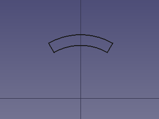
Closed profile created by two arcs and two lines.
Fusing or compounding
We now have several objects in the tree view that form a closed profile. However, this profile is still composed of disconnected objects; each of them can be edited and moved independently of the others. It is possible to continue working with the elements in this way, but it is also possible to fuse them into a single object.
6a. Note that fusing the objects into a single object will create an object that is no longer parametric, so their properties cannot be modified further.
- 6a.1. Select all four objects in the tree view, or by holding Ctrl and picking them in the 3D view.
- 6a.2. With these objects selected, click on
 Upgrade.
 - 6a.3. This will upgrade the four objects into a single
Wire.
6b. If you wish to maintain the parametric nature of the objects you can create a compound instead.
- 6b.1. Switch to the
 Part Workbench.
 - 6b.2. With these objects selected, click on
 Part Compound.
Rectangles, circles, and polygons
7. We will draw a rectangular frame. (Switch back to the ![]() Draft Workbench.)
Draft Workbench.)
- 7.1. Press
 Rectangle.
 - 7.2. Enter the values of the first point
(-100, -60, 0), and press Enter. - 7.3. Make sure the Relative option is unchecked, as we will use absolute units. You may press R in the keyboard to quickly toggle this option on and off.
- 7.4. Enter the values for the second point
(140, 90, 0), and press Enter.
A rectangle is created. Go in the property editor to change its properties. If you don't want the rectangle to create a face, set DataMake Face to false. If you want to make a face, but see only the wires of that object, keep DataMake Face to true but set the ViewDisplay Mode to Wireframe.
8. We will draw a circle.
- 8.1. Press
 Circle.
 - 8.2. Enter the values of the center
(0, 0, 0), and press Enter. - 8.3. Set the radius to
15 mm, and press Enter.
9. We will draw a regular polygon.
- 9.1. Press
 Polygon.
 - 9.2. Enter the values of the center
(0, 0, 0), and press Enter. - 9.3. Set the number of sides to
6, and press Enter. - 9.4. Set the radius to
50 mm, and press Enter.
Again, you may change the DataMake Face and ViewDisplay Mode properties in the property editor if you want.
The rectangle, the circle, the polygon, and most other objects created with the Draft Workbench share many data and view properties because they are derived from the same base class, Part Part2DObject.
![]()
Rectangle, circle and polygon added.
Arrays
Arrays are used to replicate an object several times in an orthogonal direction (X, Y, Z), around a revolution axis, or along a path.
10. We will create a polar array.
- 10.1. Select the
Wireobject that was previously created with the Upgrade tool, or the Compoundcreated with the Part Compound tool. - 10.2. Press
 PolarArray.
 - 10.3. Adjust the polar angle to
360°. - 10.4. Set the number of elements to
4. - 10.5. Enter the values for the center of rotation
(0, 0, 0), and press Enter.
The array object shows copies of the object around the origin.
![]()
Polar array of the small profile centered around the origin.
Dimensions
Linear dimensions work best when using the appropriate Draft Snap methods to select points and edges to measure. However, they can also be created by specifying absolute coordinates.
11. Create dimensions for the different objects.
- 11.1. Press
 Dimension.
 - 11.2. Pick the first point. In this tutorial the first point will always be the origin
(0, 0, 0). - 11.3. In the Snap toolbar make sure Toggle snap is active, and only
 Midpoint as well. As you move the pointer to the top edge of the polygon, the Midpoint icon should appear; click to select this point.
 - 11.4. Move the cursor to the right to specify the location of the dimension, then click to set the final position, around
(100, 20, 0). The dimension will automatically show the length value measured between the two points. - 11.5. Select the dimension object in the tree view, and in the property editor, change ViewFont Size to
6 mm, set ViewExt Lines to45 mm, and ViewShow Unit tofalse.
12. Repeat the process for the two arcs of the closed profile. The first point of the measurement will still be the origin, and the second point will use the ![]() Midpoint of the arc.
Midpoint of the arc.
13. Repeat the process for the circle located in the center. The first point of the measurement will still be the origin. To select the second point make sure ![]() Toggle snap is active, and only
Toggle snap is active, and only ![]() Angle as well. As you move the pointer to the top of the circle, the
Angle as well. As you move the pointer to the top of the circle, the ![]() Angle icon should appear; click to select this point. Then move the cursor to the right, and click to fix the dimension.
Angle icon should appear; click to select this point. Then move the cursor to the right, and click to fix the dimension.
Remember to adjust the ViewFont Size, and other properties to see the dimension correctly.
![]()
Dimensions that measure the vertical distance from the origin to the top of the circle, arcs, and polygon.
Texts and ShapeStrings
14. Text objects are simple planar figures that are created in the 3D view but don't have an actual "shape" underneath. This means that they cannot be used in complex operations with shapes like extrusions or boolean operations.
- 14.1. Press
 Text.
Text. - 14.2. Select the reference point in the 3D view. In the Snap toolbar make sure Toggle snap is active, and only Midpoint as well. Move the pointer to the top edge of the highest arc, so that the Midpoint icon appears; click to select this point.
- 14.3. Enter the desired Text, and press Enter once to start a new line; add more lines of text as needed.
- 14.4. When you are ready to finish with edition, press Enter twice.
- 14.5. Select the text object in the tree view, and in the property editor, change ViewFont Size to
6 mm, and ViewJustification toCenter.
15. ShapeString objects are shapes made of primitive wires that follow the lines indicated by a certain font. This means that these objects have a real "shape" underneath, and thus can be used in complex operations like extrusions and boolean operations.
- 15.1. Press
 ShapeString.
 - 15.2. Move the pointer to the desired location in the 3D view above the regular polygon, and click once. This will fix the base point for the ShapeString. The coordinates may be entered manually as well, for example,
(-20, 65, 0). - 15.3. Enter the desired String, and choose the desired Height.
- 15.4. If there is no default font file, you must click on the ellipsis ... to open a dialog window to choose the font location in the system.
- 15.5. When a valid font file has been specified, you may proceed to click OK or press Enter.
![]()
Text and ShapeString objects added.
To extrude letters and engrave them on to solids, see the Draft ShapeString tutorial.
Creating technical drawings
As it is now, the objects that we have created can be saved, exported to other formats like SVG or DXF, or printed.
If you wish, you may create a technical drawing to display these objects together with additional information like a frame.
Before doing anything, hide the Draft grid by pressing ![]() Toggle grid.
Toggle grid.
16. Switch to the ![]() TechDraw Workbench.
TechDraw Workbench.
- 16.1. Create a standard page by pressing
 TechDraw PageDefault.
 - 16.2. In the tree view select all objects created, except for the Page, and then press
 TechDraw ActiveView. Press OK with the default options; it may take a few seconds to create the view in the page.
 - 16.3. Selecting the Page object in the tree view will automatically display the Page in the main window. With the Page selected, go to the property editor, and change DataScale to
0.75. - 16.4. Expand the Page object in the tree view to select the ActiveView object. With this view selected, go to the property editor, and change DataScale Type to
Page. - 16.5. Recompute the model by using Refresh or pressing F5.
- 16.6. Hide the frames of the objects by pressing
 TechDraw ToggleFrame.
Learn more about the TechDraw Workbench by reading the Basic TechDraw Tutorial.
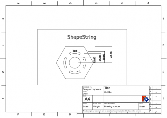
TechDraw page with a projection of the shapes created with the Draft Workbench.
TechDraw works best with objects that have a Part TopoShape. Since some objects from Draft, like Draft Texts and Draft Dimensions, don't have such "shapes", some operations of TechDraw don't work with these elements.
Tools like ![]() TechDraw ActiveView,
TechDraw ActiveView, ![]() TechDraw DraftView, and
TechDraw DraftView, and ![]() TechDraw ArchView work by receiving an internal SVG image that is generated by internal Draft functions; therefore, TechDraw doesn't have much control about how these views are displayed. More integration of Draft and TechDraw is a work in progress.
TechDraw ArchView work by receiving an internal SVG image that is generated by internal Draft functions; therefore, TechDraw doesn't have much control about how these views are displayed. More integration of Draft and TechDraw is a work in progress.
Final remarks
The Draft Workbench in many ways is similar to the Sketcher Workbench, as both are intended to produce 2D shapes. The main difference is in the way each workbench handles coordinate systems, and how the objects are positioned. In Draft, objects are freely positioned in the global coordinates system, usually snapping their points to a grid, or to other objects. In Sketcher, a "sketch object" defines a local coordinate system which serves as the reference for all geometrical elements within that sketch. Moreover, the sketch relies on "constraints" to define the final position of its points.
- The Draft Workbench is intended for 2D drawings which are suitable to be drawn on a grid. The BIM Workbench mostly builds on top of the tools defined in the Draft Workbench.
- The Sketcher Workbench is intended for 2D drawings that require precise relationships between its points. It does not rely on a grid, but on rules of positioning (constraints) to determine where the points and edges will be placed. The Sketcher Workbench is mostly used together with the PartDesign Workbench for the creation of solid bodies.
- It is possible to transform a Draft object into a Sketch, and the other way around, using the
 Draft Draft2Sketch tool.
- Drafting: Line, Polyline, Fillet, Arc, Arc by 3 points, Circle, Ellipse, Rectangle, Polygon, B-spline, Cubic Bézier curve, Bézier curve, Point, Facebinder, ShapeString, Hatch
- Annotation: Text, Dimension, Label, Annotation styles, Annotation scale
- Modification: Move, Rotate, Scale, Mirror, Offset, Trimex, Stretch, Clone, Array, Polar array, Circular array, Path array, Path link array, Point array, Point link array, Edit, Subelement highlight, Join, Split, Upgrade, Downgrade, Wire to B-spline, Draft to sketch, Set slope, Flip dimension, Shape 2D view
- Draft Tray: Select plane, Set style, Toggle construction mode, AutoGroup
- Snapping: Snap lock, Snap endpoint, Snap midpoint, Snap center, Snap angle, Snap intersection, Snap perpendicular, Snap extension, Snap parallel, Snap special, Snap near, Snap ortho, Snap grid, Snap working plane, Snap dimensions, Toggle grid
- Miscellaneous: Apply current style, Layer, Manage layers, Add a new named group, Move to group, Select group, Add to construction group, Toggle normal/wireframe display, Create working plane proxy, Heal, Show snap toolbar
- Additional: Constraining, Pattern, Preferences, Import Export Preferences, DXF/DWG, SVG, OCA, DAT
- Context menu:
- Layer container: Merge layer duplicates, Add new layer
- Layer: Activate this layer, Select layer contents
- Text: Open hyperlinks
- Wire: Flatten
- Working plane proxy: Write camera position, Write objects state
- Getting started
- Installation: Download, Windows, Linux, Mac, Additional components, Docker, AppImage, Ubuntu Snap
- Basics: About FreeCAD, Interface, Mouse navigation, Selection methods, Object name, Preferences, Workbenches, Document structure, Properties, Help FreeCAD, Donate
- Help: Tutorials, Video tutorials
- Workbenches: Std Base, Assembly, BIM, CAM, Draft, FEM, Inspection, Material, Mesh, OpenSCAD, Part, PartDesign, Points, Reverse Engineering, Robot, Sketcher, Spreadsheet, Surface, TechDraw, Test Framework
- Hubs: User hub, Power users hub, Developer hub