Урок по черчению
| Тема |
|---|
| Черчение |
| Уровень |
| Начинающий |
| Время для завершения |
| 30 минут |
| Авторы |
| Drei и vocx |
| FreeCAD версия |
| 0.19 |
| Примеры файлов |
| Draft tutorial updated |
| Смотрите также |
| None |
Введение
Этот учебник изначально написан Drei, переписан и иллюстрирован vocx.
Урок знакомит пользователя с основами рабочего процесса Верстака Draft.
Читатель будет практиковаться в:
- создании линий, дуг и полигонов
- использование рабочих поверхностей
- создании размеров, текста и надписей
- создании технических чертежей
В уроке используется обозначение (x, y, z) для указания координат точки объекта. Размеры по умолчанию в миллиметрах mm.
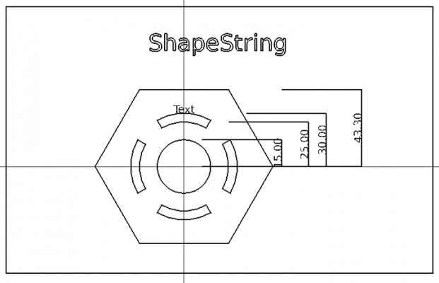
Итоговый чертёж с различными объектами Draft.
Настройка
1. Запустите FreeCAD, создайте новый пустой документ из меню Файл → Создать.
- 1.1. Переключитесь на верстак Draft из списка верстаков или из меню Вид → Рабочее окружение →
Draft.
- 1.2. Убедитесь, что вы понимаете как использовать редактор свойств, а в особенности вкладки Данные и Вид для изменения свойств. При изменении свойств, вы можете
Обновлять 3D-вид view для отображения результата.
- 1.3. Так как объекты Draft это плоские фигуры, их лучше отображать видом сверху. Используйте кнопку
Вид сверху для 3D-вида.
- 1.4. Хотя в этом уроке и не используется сетка в верстаке Draft, она полезна для размещения геометрических элементов. Используйте
Выбор плоскости для установки рабочей плоскости и сетки, затем включайте или выключайте сетку при помощи
Показывать сетку.
Панель инструментов привязки
2. Панель привязки Draft обычно активирована, если вы переключаетесь на верстак Draft.
- 2.1. Чтобы убедиться, в её активности перейдите в Настройки Draft, Правка → Настройки → Draft → Сетка и привязка.
- 2.2. Проверьте, что активно Показать панель инструментов привязки.
Вы так же можете изменить в этом окне видимость и параметры сетки Draft.
Рабочие плоскости
Большинство объектов Draft являются плоскими фигурами, поэтому естественно, что они располагаются на рабочей плоскости. Рабочая плоскость может быть одна из основных XY, XZ или YZ глобальных координатных плоскостей или параллельна им с положительным или отрицательным смещением. Также это может быть плоскость заданная поверхностью твердого объекта.
3. Нажмите Выбор плоскости или из меню Вспомогательные →
Выбор плоскости чтобы открыть панель задач.
Перед тем как нажать кнопку, вы можете изменить значение смещения в мм, а также расстояние сетки, основные линии и радиус привязки.
Линии и дуги
4. Создадим дуги и линии.
- 4.1. Нажмите
Дуга.
- 4.2. Установите Центр в
(0, 0, 0)и нажмите Enter. - 4.3. Установите Радиус в
30 mmи нажмите Enter. - 4.4. Установите Начальный угол в
60.0°и нажмите Enter. - 4.5. Установите Угол апертуры в
60.0°и нажмите Enter. - 4.6. Повторите эту процедуру для следующей дуги с радиусом
25 мм, остальные параметры те же.
5. Теперь создадим замкнутый профиль, связав дуги с линиями.
- 5.1. Нажмите
Line.
- 5.2. В Snap toolbar убедитесь, что
режим привязки активен, с одним только
Endpoint вдобавок. Когда Вы придвините указатель к конечной точке дуги, появится иконка
Endpoint. Кликните для выбора этой точки.
- 5.3. Переместите указатель к ближайшей конечной точке другой дуги, чтобы связать две дуги вместе.
- 5.4. Повторите процесс для другой стороны дуги, чтобы закрыть профиль.
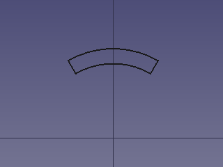
Замкнутый контур из двух дуг и двух линий.
Fusing or compounding
Теперь в древе проекта есть несколько объектов, которые образуют закрытый профиль. Однако этот профиль все еще состоит из отключенных объектов; каждый из них может быть отредактирован и перемещен независимо от других. Возможно продолжить работу с отдельными элементами как они есть, но в данном случае мы объединим их в один объект.
6а. Обратите внимание, что объединение объектов в один объект приведет к созданию объекта, который больше не является параметрическим, поэтому их свойства не могут быть изменены в дальнейшем.
- 6a.1. Выберите все четыре объекта в древе проекта, или, удерживая Ctrl, выберите их в трёхмерном виде.
- 6a.2. Выбрав эти объекты, нажмите
Upgrade.
- 6a.3. Это обновит четыре объекта в один
Wire.
6b. If you wish to maintain the parametric nature of the objects you can create a compound instead.
- 6b.1. Switch to the
Part Workbench.
- 6b.2. With these objects selected, click on
Part Compound.
Прямоугольники, окружности и полигоны
7. We will draw a rectangular frame. (Switch back to the Draft Workbench.)
- 7.1. Press
Rectangle.
- 7.2. Enter the values of the first point
(-100, -60, 0), and press Enter. - 7.3. Make sure the Relative option is unchecked, as we will use absolute units. You may press R in the keyboard to quickly toggle this option on and off.
- 7.4. Enter the values for the second point
(140, 90, 0), and press Enter.
A rectangle is created. Go in the property editor to change its properties. If you don't want the rectangle to create a face, set ДанныеMake Face to false. If you want to make a face, but see only the wires of that object, keep ДанныеMake Face to true but set the ВидDisplay Mode to Wireframe.
8. Нарисуем круг.
- 8.1. Нажмите
Circle.
- 8.2. Введите значения центра
(0, 0, 0)и нажмите Enter. - 8.3. Установите радиус
15 mmи нажмите Enter.
9. Нарисуем правильный многоугольник.
- 9.1. Нажмите
Polygon.
- 9.2. Введите значения центра
(0, 0, 0)и нажмите Enter. - 9.3. Установите количество сторон
6и нажмите Enter. - 9.4. Установите радиус
50 мми нажмите Enter.
Again, you may change the ДанныеMake Face and ВидDisplay Mode properties in the property editor if you want.
The rectangle, the circle, the polygon, and most other objects created with the Draft Workbench share many data and view properties because they are derived from the same base class, Part Part2DObject.
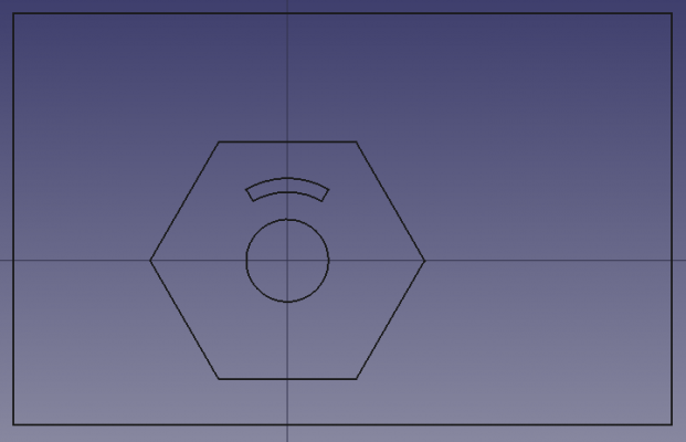
Rectangle, circle and polygon added.
Arrays
Arrays are used to replicate an object several times in an orthogonal direction (X, Y, Z), around a revolution axis, or along a path.
10. We will create a polar array.
- 10.1. Select the
Wireobject that was previously created with theUpgrade tool, or the
Compoundcreated with thePart Compound tool.
- 10.2. Press
PolarArray.
- 10.3. Adjust the polar angle to
360°. - 10.4. Set the number of elements to
4. - 10.5. Enter the values for the center of rotation
(0, 0, 0), and press Enter.
The array object shows copies of the object around the origin.
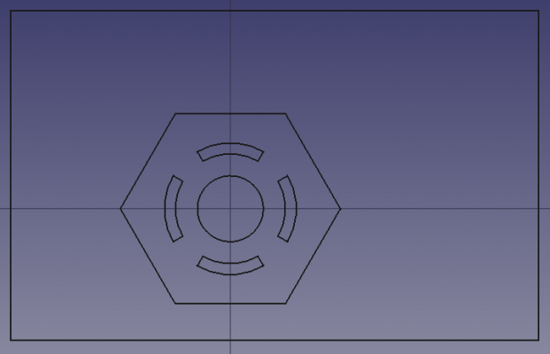
Polar array of the small profile centered around the origin.
Dimensions
Linear dimensions work best when using the appropriate Draft Snap methods to select points and edges to measure. However, they can also be created by specifying absolute coordinates.
11. Create dimensions for the different objects.
- 11.1. Press
Dimension.
- 11.2. Pick the first point. In this tutorial the first point will always be the origin
(0, 0, 0). - 11.3. In the Snap toolbar make sure
Toggle snap is active, and only
Midpoint as well. As you move the pointer to the top edge of the polygon, the
Midpoint icon should appear; click to select this point.
- 11.4. Move the cursor to the right to specify the location of the dimension, then click to set the final position, around
(100, 20, 0). The dimension will automatically show the length value measured between the two points. - 11.5. Select the dimension object in the tree view, and in the property editor, change ВидFont Size to
6 mm, set ВидExt Lines to45 mm, and ВидShow Unit tofalse.
12. Повторите процесс для двух дуг замкнутого профиля. Первая точка измерения по-прежнему будет в исходной, а вторая точка будет использовать среднюю точку дуги.
13. Repeat the process for the circle located in the center. The first point of the measurement will still be the origin. To select the second point make sure Toggle snap is active, and only
Angle as well. As you move the pointer to the top of the circle, the
Angle icon should appear; click to select this point. Then move the cursor to the right, and click to fix the dimension.
Remember to adjust the ВидFont Size, and other properties to see the dimension correctly.
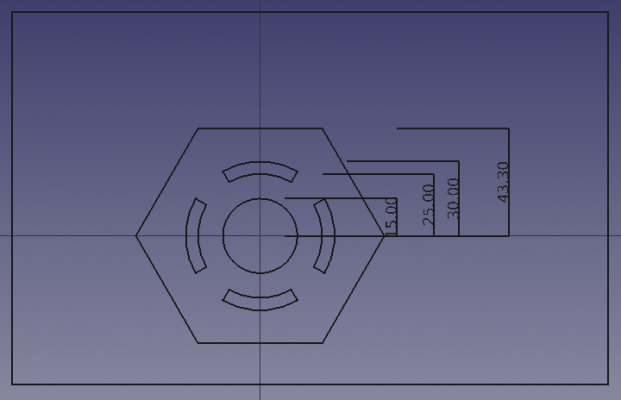
Dimensions that measure the vertical distance from the origin to the top of the circle, arcs, and polygon.
Texts and ShapeStrings
14. Text objects are simple planar figures that are created in the 3D view but don't have an actual "shape" underneath. This means that they cannot be used in complex operations with shapes like extrusions or boolean operations.
- 14.1. Press
Text.
- 14.2. Select the reference point in the 3D view. In the Snap toolbar make sure
Toggle snap is active, and only
Midpoint as well. Move the pointer to the top edge of the highest arc, so that the
Midpoint icon appears; click to select this point.
- 14.3. Enter the desired Text, and press Enter once to start a new line; add more lines of text as needed.
- 14.4. When you are ready to finish with edition, press Enter twice.
- 14.5. Select the text object in the tree view, and in the property editor, change ВидFont Size to
6 mm, and ВидJustification toCenter.
15. ShapeString objects are shapes made of primitive wires that follow the lines indicated by a certain font. This means that these objects have a real "shape" underneath, and thus can be used in complex operations like extrusions and boolean operations.
- 15.1. Press
ShapeString.
- 15.2. Move the pointer to the desired location in the 3D view above the regular polygon, and click once. This will fix the base point for the ShapeString. The coordinates may be entered manually as well, for example,
(-20, 65, 0). - 15.3. Enter the desired String, and choose the desired Height.
- 15.4. If there is no default font file, you must click on the ellipsis ... to open a dialog window to choose the font location in the system.
- 15.5. When a valid font file has been specified, you may proceed to click OK or press Enter.
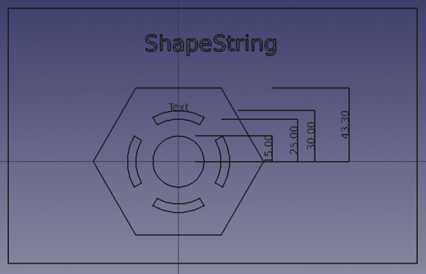
Text and ShapeString objects added.
To extrude letters and engrave them on to solids, see the Draft ShapeString tutorial.
Creating technical drawings
As it is now, the objects that we have created can be saved, exported to other formats like SVG or DXF, or printed.
If you wish, you may create a technical drawing to display these objects together with additional information like a frame.
Before doing anything, hide the Draft grid by pressing Toggle grid.
16. Switch to the TechDraw Workbench.
- 16.1. Create a standard page by pressing
TechDraw PageDefault.
- 16.2. In the tree view select all objects created, except for the Page, and then press
TechDraw ActiveView. Press OK with the default options; it may take a few seconds to create the view in the page.
- 16.3. Selecting the Page object in the tree view will automatically display the Page in the main window. With the Page selected, go to the property editor, and change ДанныеScale to
0.75. - 16.4. Expand the Page object in the tree view to select the ActiveView object. With this view selected, go to the property editor, and change ДанныеScale Type to
Page. - 16.5. Recompute the model by using
Refresh or pressing F5.
- 16.6. Hide the frames of the objects by pressing
TechDraw ToggleFrame.
Learn more about the TechDraw Workbench by reading the Basic TechDraw Tutorial.
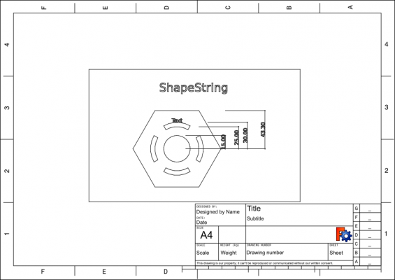
TechDraw page with a projection of the shapes created with the Draft Workbench.
TechDraw works best with objects that have a Part TopoShape. Since some objects from Draft, like Draft Texts and Draft Dimensions, don't have such "shapes", some operations of TechDraw don't work with these elements.
Tools like TechDraw ActiveView,
TechDraw DraftView, and
TechDraw ArchView work by receiving an internal SVG image that is generated by internal Draft functions; therefore, TechDraw doesn't have much control about how these views are displayed. More integration of Draft and TechDraw is a work in progress.
Конечные замечания
The Draft Workbench in many ways is similar to the Sketcher Workbench, as both are intended to produce 2D shapes. The main difference is in the way each workbench handles coordinate systems, and how the objects are positioned. In Draft, objects are freely positioned in the global coordinates system, usually snapping their points to a grid, or to other objects. In Sketcher, a "sketch object" defines a local coordinate system which serves as the reference for all geometrical elements within that sketch. Moreover, the sketch relies on "constraints" to define the final position of its points.
- The Draft Workbench is intended for 2D drawings which are suitable to be drawn on a grid. The BIM Workbench mostly builds on top of the tools defined in the Draft Workbench.
- The Sketcher Workbench is intended for 2D drawings that require precise relationships between its points. It does not rely on a grid, but on rules of positioning (constraints) to determine where the points and edges will be placed. The Sketcher Workbench is mostly used together with the PartDesign Workbench for the creation of solid bodies.
- It is possible to transform a Draft object into a Sketch, and the other way around, using the
Draft Draft2Sketch tool.
- Drafting: Line, Polyline, Fillet, Arc, Arc by 3 points, Circle, Ellipse, Rectangle, Polygon, B-spline, Cubic Bézier curve, Bézier curve, Point, Facebinder, ShapeString, Hatch
- Annotation: Text, Dimension, Label, Annotation styles, Annotation scale
- Modification: Move, Rotate, Scale, Mirror, Offset, Trimex, Stretch, Clone, Array, Polar array, Circular array, Path array, Path link array, Point array, Point link array, Edit, Subelement highlight, Join, Split, Upgrade, Downgrade, Wire to B-spline, Draft to sketch, Set slope, Flip dimension, Shape 2D view
- Draft Tray: Select plane, Set style, Toggle construction mode, AutoGroup
- Snapping: Snap lock, Snap endpoint, Snap midpoint, Snap center, Snap angle, Snap intersection, Snap perpendicular, Snap extension, Snap parallel, Snap special, Snap near, Snap ortho, Snap grid, Snap working plane, Snap dimensions, Toggle grid
- Miscellaneous: Apply current style, Layer, Manage layers, Add a new named group, Move to group, Select group, Add to construction group, Toggle normal/wireframe display, Create working plane proxy, Heal, Show snap toolbar
- Additional: Constraining, Pattern, Preferences, Import Export Preferences, DXF/DWG, SVG, OCA, DAT
- Context menu:
- Layer container: Merge layer duplicates, Add new layer
- Layer: Activate this layer, Select layer contents
- Text: Open hyperlinks
- Wire: Flatten
- Working plane proxy: Write camera position, Write objects state
- Начинающим
- Установка: Загрузка, Windows, Linux, Mac, Дополнительных компонентов, Docker, AppImage, Ubuntu Snap
- Базовая: О FreeCAD, Интерфейс, Навигация мыши, Методы выделения, Имя объекта, Настройки, Верстаки, Структура документа, Свойства, Помоги FreeCAD, Пожертвования
- Помощь: Учебники, Видео учебники
- Верстаки: Std Base, Arch, Assembly, CAM, Draft, FEM, Inspection, Mesh, OpenSCAD, Part, PartDesign, Points, Reverse Engineering, Robot, Sketcher, Spreadsheet, Surface, TechDraw, Test Framework


