
Whiffle Ball tutorial
| Topic |
|---|
| Product design |
| Level |
| Beginner |
| Time to complete |
| 30 minutes |
| Authors |
| r-frank and vocx |
| FreeCAD version |
| 0.17 and above |
| Example files |
| WhiffleBall_Tutorial_FCWiki.FCStd |
| See also |
| None |
Introduction
This tutorial was originally written by Roland Frank (†2017, r-frank), and it was rewritten and illustrated by vocx.
This tutorial is here to teach you how to use the Part Workbench.
The Part Workbench was the first workbench developed. It provides the basic geometrical elements that can be used as building blocks for other workbenches. The Part Workbench is meant to be used in a traditional constructive solid geometry (CSG) workflow. For a more modern workflow using sketches, pads, and features, use the PartDesign Workbench.
You will practice:
- inserting primitives
- changing parameters of those primitive objects
- modifying their placement
- doing boolean operations
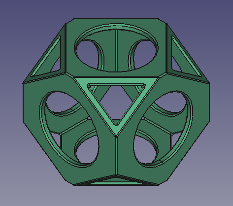
Final model of the wiffle ball
Setup
1. Open FreeCAD, create a new empty document with File → ![]() New, and switch to the Part Workbench.
New, and switch to the Part Workbench.
- 1.1. Press the
 View isometric button, or press 0 in the numerical pad of your keyboard, to change the view to isometric to visualize the 3D solids better.
 - 1.2. Press the
 View fit all button whenever you add objects in order to pan and zoom the 3D view so that all elements are seen in the view.
 - 1.3. Hold Ctrl while you click to select multiple items. If you selected something wrong or want to de-select everything, just click on empty space in the 3D view.
Insert primitive cubes
2. Insert a primitive cube by clicking on ![]() Box.
Box.
- 2.1. Select
Cubein the tree view. - 2.2. Change the dimensions in the Data tab of the property editor.
- 2.3. Change Length to
90 mm. - 2.4. Change Width to
90 mm. - 2.5. Change Height to
90 mm.
3. In the Data tab of the property editor, click on the Placement value so the ellipsis button ... appears on the right.
- 3.1. Press on the ellipsis to launch the Placement dialog.
- 3.2. Change the Translation values.
- 3.3. Change X to
-45 mm. - 3.4. Change Y to
-45 mm. - 3.5. Change Z to
-45 mm. - 3.6. Press the OK button to close the dialog.
4. Repeat the process, inserting a second, smaller cube by clicking on ![]() Box.
Box.
- 4.1. The second cube will be created with the same name, but with an additional number to distinguish the object.
- 4.2. Select
Cube001in the tree view, and change the dimensions and placement like with the previous object. - 4.3. Change Length to
80 mm. - 4.4. Change Width to
80 mm. - 4.5. Change Height to
80 mm. - 4.6. Open the Placement dialog.
- 4.7. Change X to
-40 mm. - 4.8. Change Y to
-40 mm. - 4.9. Change Z to
-40 mm. - 4.10. Press the OK button to close the dialog.
Change visual properties
5. The previous operations create a smaller cube inside a bigger cube. To visualize this, we can modify the View properties in the property editor.
- 5.1. Select
Cube001, the smaller cube, in the tree view, and change the color. In the View tab, click on the Shape Color value to open the Select color dialog, then choose a green color; also change the value of Line Width to2.0. - 5.2. Select
Cube, the larger cube, in the tree view. In the View tab, change the value of Transparency to70.
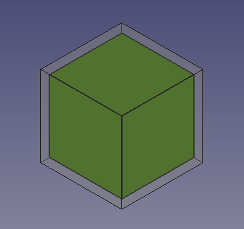
Solid cube inside another solid cube
Insert primitive cylinders
6. Insert a primitive cylinder by clicking on ![]() Cylinder.
Cylinder.
- 6.1. Select
Cylinderin the tree view. - 6.2. Change the dimensions in the Data tab of the property editor.
- 6.3. Change Radius to
27.5 mm. - 6.4. Change Height to
120 mm. - 6.5. Open the Placement dialog.
- 6.6. Change Z to
-60 mm. - 6.7. Press the OK button to close the dialog.
7. Repeat the process, inserting a second cylinder by clicking on ![]() Cylinder.
Cylinder.
- 7.1. The second cylinder will be created with the same name, but with an additional number to distinguish the object.
- 7.2. Select
Cylinder001in the tree view, and change the dimensions and placement like with the previous object. - 7.3. Change Radius to
27.5 mm. - 7.4. Change Height to
120 mm. - 7.5. Open the Placement dialog.
- 7.6. Change Y to
60 mm. - 7.7. Change the Rotation to
Rotation axis with angle; Axis toX(by setting theX,YandZvalues of the axis inputboxes to1,0and0respectively), and Angle to90 deg. - 7.8. Press the OK button to close the dialog.
8. Insert another cylinder. This time create a duplicate so that the radius and height don't have to be changed, only its placement.
- 8.1. Select
Cylinder001in the tree view, and go to the menu Edit → Duplicate selection. This will createCylinder002. - 8.2. Open the Placement dialog.
- 8.3. Change X to
-60 mm, and change Y back to0 mm. - 8.4. Change the Rotation to
Rotation axis with angle; Axis toY, and Angle to90 deg. - 8.5. Press the OK button to close the dialog.
Change visual properties
9. The previous operations create three cylinders that intersect with each other, and also intersect the cubes. To visualize this better we can modify the View properties in the property editor.
- 9.1. Select
Cube001, the smaller cube, in the tree view, and change the transparency. In the View tab, change the value of Transparency to70. - 9.2. Select
Cylinder, in the View tab, click on the Shape Color value to open the Select color dialog, then choose a red color. - 9.3. Select
Cylinder001, in the View tab, click on the Shape Color value to open the Select color dialog, then choose a blue color. - 9.4. Select
Cylinder002, in the View tab, click on the Shape Color value to open the Select color dialog, then choose a pink color. - 9.5. Select the three cylinders, in the View tab also change the value of Line Width to
2.0.
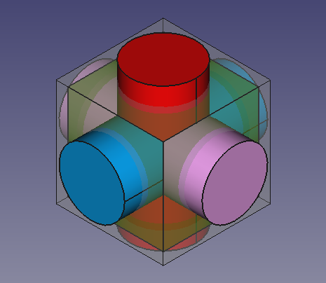
Solid cylinders that intersect themselves and the solid cubes.
Fuse and cut
10. In the tree view, select Cube001 (the inner, smaller cube), and the tree cylinders, then press ![]() Fuse. This will create a
Fuse. This will create a Fusion object.
11. Then perform a boolean cut of the Cube (larger cube) and the new Fusion object.
- 11.1. In the tree view select
Cubefirst, and thenFusion. - 11.2. Then press
 Cut. This will create a
 Cutobject. - Note: the order in which you select the objects is important for the cut operation. The base object is selected first, and the subtracting object comes at the end.
- 11.3. If the colors look strange, select the new
Cutobject, go to the View tab, click on the Shape Color value to open the Select color dialog, then choose a gray color; also change the value of Line Width to2.0.
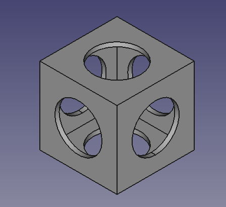
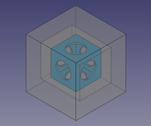
Hollow shape produced from cutting a cube and three cylinders from a bigger cube.
Insert primitive cubes to cut the corners of the partial solid
Now we'll create more cubes that will be used as cutting tools to trim the corners of the previously obtained Cut object.
12. Click on ![]() Box.
Box.
- 12.1. Select
Cube002in the tree view, and change the dimensions and placement. - 12.2. Change Length to
140 mm. - 12.3. Change Width to
112 mm. - 12.4. Change Height to
112 mm. - 12.5. Open the Placement dialog.
- 12.6. Change X to
-70 mm. - 12.7. Change Y to
-56 mm. - 12.8. Change Z to
-56 mm. - 12.9. Press OK.
13. Click on ![]() Box.
Box.
- 13.1. Select
Cube003in the tree view, and change the dimensions and placement. - 13.2. Change Length to
180 mm. - 13.3. Change Width to
180 mm. - 13.4. Change Height to
180 mm. - 13.5. Open the Placement dialog.
- 13.6. Change X to
-90 mm. - 13.7. Change Y to
-90 mm. - 13.8. Change Z to
-90 mm. - 13.9. Press OK.
We'll duplicate the previous two objects again to use once more as cutting objects.
14. Select only Cube002 in the tree view, and go to Edit → Duplicate selection. This will create Cube004.
15. Select only Cube003 in the tree view, and go to Edit → Duplicate selection. This will create Cube005.
16. To visualize this better we can modify the View properties in the property editor.
- 16.1. Select the
Cutobject, in the View tab, click on the Shape Color value to open the Select color dialog, then choose a blue color. - 16.2. Select all new cubes,
Cube002,Cube003,Cube004, andCube005, in the View tab, change the value of Transparency to80.
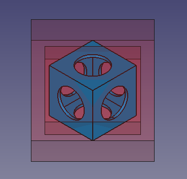
Additional external cubes that will be used as cutting objects for the internal solid.
Cutting the corners 1
17. In the tree view select Cube002 and Cube003.
- 17.1. Open the Placement dialog.
- 17.2. Tick the option Apply incremental changes; notice that all Translation values are reset to zeroes.
- 17.3. Change the Rotation to
Rotation axis with angle; Axis toX, and Angle to45 deg, then click on Apply. This will apply a rotation around the X-axis, and will reset the Angle field to zero. - 17.4. Change the Rotation again, now Axis to
Z, and Angle to45 deg, then click on Apply. This will apply a rotation around the local Z-axis, and will reset the Angle field to zero. - 17.5. Click on OK to close the dialog.
18. In the tree view de-select the objects; then select Cube003 first, the bigger cube, and then Cube002, the smaller cube.
- 18.1. Then press Cut. This will create
Cut001. This is a hollowed body which intersects the initialCutonly at certain corners.
19. To visualize this better we can modify the View properties in the property editor.
- 19.1. Select
Cube004andCube005, in the View tab, then change the value of Visibility tofalse, or press Space in the keyboard. - 19.2. Select
Cut001, click on the Shape Color value to open the Select color dialog, then choose a red color; also change the value of Transparency to90.
A rotated, hollowed solid, which will be used as a cutting object for some corners of the internal solid.
Cutting the corners 2
20. In the tree view select Cut001, in the View tab, change the value of Visibility to false, or press Space in the keyboard.
21. In the tree view select Cube004 and Cube005, in the View tab, change the value of Visibility to true, or press Space in the keyboard.
- 21.1. Open the Placement dialog.
- 21.2. Tick the option Apply incremental changes; notice that all Translation values are reset to zeroes.
- 21.3. Change the Rotation to
Rotation axis with angle; Axis toX, and Angle to45 deg, then click on Apply. This will apply a rotation around the X-axis, and will reset theAnglefield to zero. - 21.4. Change the Rotation again, now Axis to
Z, and Angle to-45 deg, then click on Apply. This will apply a rotation around the local Z-axis, and will reset the Angle field to zero. - 21.5. Click on OK to close the dialog.
22. In the tree view de-select the objects; then select Cube005 first, the bigger cube, and then Cube004, the smaller cube.
- 22.1. Then press Cut. This will create
Cut002. This is a hollowed body which intersects the initialCutonly at certain corners.
23. To visualize this better we can modify the View properties in the property editor.
- 23.1. Select
Cut002, click on the Shape Color value to open the Select color dialog, then choose a pink color; also change the value of Transparency to90.
A rotated, hollowed solid, which will be used as a cutting object for some corners of the internal solid.
Finishing the model
24. Make sure all objects are visible. In the tree view select all objects, in the View tab, change the value of Visibility to true, or press Space in the keyboard.
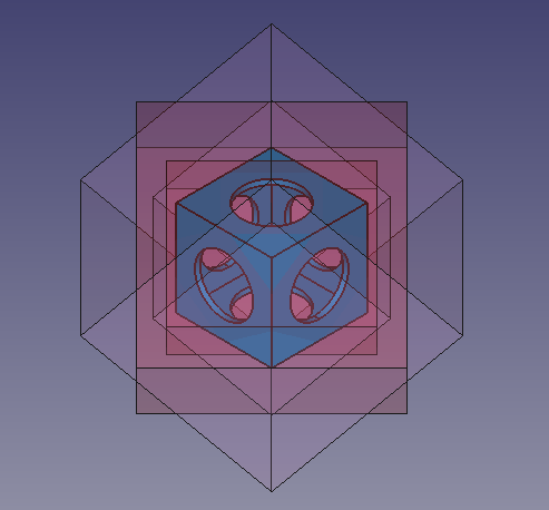
The internal hollowed solid, together with the external objects which will be used to cut it.
25. In the tree view de-select the objects; then select Cut first, and then Cut001.
- 25.1. Then press Cut. This will create
Cut003.
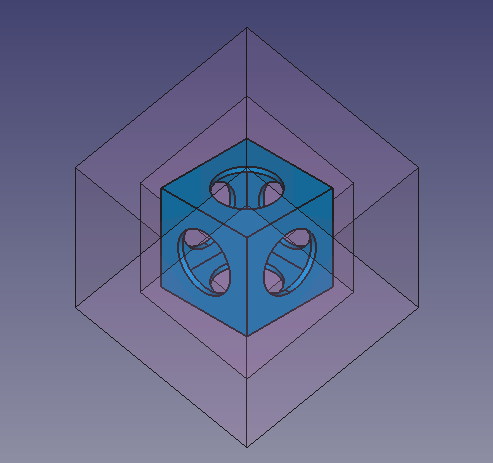
The internal hollowed solid, cut by Cut001.
26. In the tree view de-select the objects; then select Cut003 first, and then Cut002.
- 26.1. Then press Cut. This will create
Cut004. This is the final object. - 26.2. Select
Cut004, click on the Shape Color value to open the Select color dialog, then choose a green color; also change the value of Line Width to2.0.
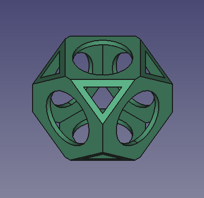
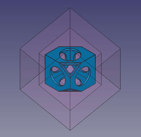
The internal hollowed solid, cut by Cut001 and Cut002. Final model.
27. Real objects don't have perfectly sharp edges or corners, so applying a fillet to the edges can be done to refine the model.
- 27.1. In the tree view, select
Cut004then press Fillet.
 - 27.2. In the Fillet edges task panel go to Selection, choose Select edges, and then press All. As Fillet type choose
Constant radius, then set Radius to1 mm. - 24.3. Press OK. This will create a
Filletobject. - 27.4. In the View tab, change the value of Line Width to
2.0.
Final whiffle ball model with fillets applied to the edges.
- Primitives: Box, Cylinder, Sphere, Cone, Torus, Tube, Create primitives, Shape builder
- Creation and modification: Create sketch, Extrude, Revolve, Mirror, Scale, Fillet, Chamfer, Make face from wires, Ruled Surface, Loft, Sweep, Section, Cross sections, 3D Offset, 2D Offset, Thickness, Projection on surface, Color per face
- Boolean: Make compound, Explode compound, Compound Filter, Boolean, Cut, Union, Intersection, Connect objects, Embed object, Cutout for object, Boolean fragments, Slice apart, Slice to compound, Boolean XOR, Check geometry, Defeaturing
- Other tools: Import CAD file, Export CAD file, Box selection, Create shape from mesh, Create points object from geometry, Convert to solid, Reverse shapes, Create simple copy, Create transformed copy, Create shape element copy, Refine shape, Attachment
- Preferences: Preferences, Fine tuning
- Getting started
- Installation: Download, Windows, Linux, Mac, Additional components, Docker, AppImage, Ubuntu Snap
- Basics: About FreeCAD, Interface, Mouse navigation, Selection methods, Object name, Preferences, Workbenches, Document structure, Properties, Help FreeCAD, Donate
- Help: Tutorials, Video tutorials
- Workbenches: Std Base, Assembly, BIM, CAM, Draft, FEM, Inspection, Material, Mesh, OpenSCAD, Part, PartDesign, Points, Reverse Engineering, Robot, Sketcher, Spreadsheet, Surface, TechDraw, Test Framework
- Hubs: User hub, Power users hub, Developer hub